
Closed-loop planar linear motor with integral monolithic three-degree-of-freedom AC-magnetic position/orientation sensor

a closed-loop, linear motor technology, applied in the direction of ignition automatic control, dynamo-electric converter control, program control, etc., can solve the problems of inability to reject low-frequency external disturbances, inability to maintain synchrony, and limited current planar motion systems, etc., to achieve precise signals for closed-loop control, high quality position, and easy manufacturing

Inactive Publication Date: 2001-01-16
RALPH L HOLLIS JR
View PDF12 Cites 73 Cited by
  • Summary
  • Abstract
  • Description
  • Claims
  • Application Information

AI Technical Summary

Benefits of technology

The present invention is a precision closed-loop planar motor with an integrated monolithic sensor that is insensitive to scratches and other contaminants, providing high quality position signals for precise closed-loop control. The sensor is easily manufacturable and capable of measuring all degrees of freedom in the plane, providing precise signals for closed-loop control. The forcer of the motor can execute precise motion in translation in two orthogonal directions, and small rotations in the plane.

Problems solved by technology

The patent text describes a problem in the design of sensors for planar motors. Current methods of optical and magnetic sensors have limitations such as susceptibility to scratches, dirt, and contamination. The text proposes a new sensor design that is not affected by these issues. The technical problem is to provide a closed-loop planar motor with a monolithic sensor that can measure the position and orientation of the platen teeth with high precision. The sensor is insensitive to scratches and can be easily integrated into existing motor designs.

Method used


Image

  • Closed-loop planar linear motor with integral monolithic three-degree-of-freedom AC-magnetic position/orientation sensor
  • Closed-loop planar linear motor with integral monolithic three-degree-of-freedom AC-magnetic position/orientation sensor
  • Closed-loop planar linear motor with integral monolithic three-degree-of-freedom AC-magnetic position/orientation sensor

Examples


Embodiment Construction

. 1A, 1B, 2, 3A, 3B, 4-7, AND 9

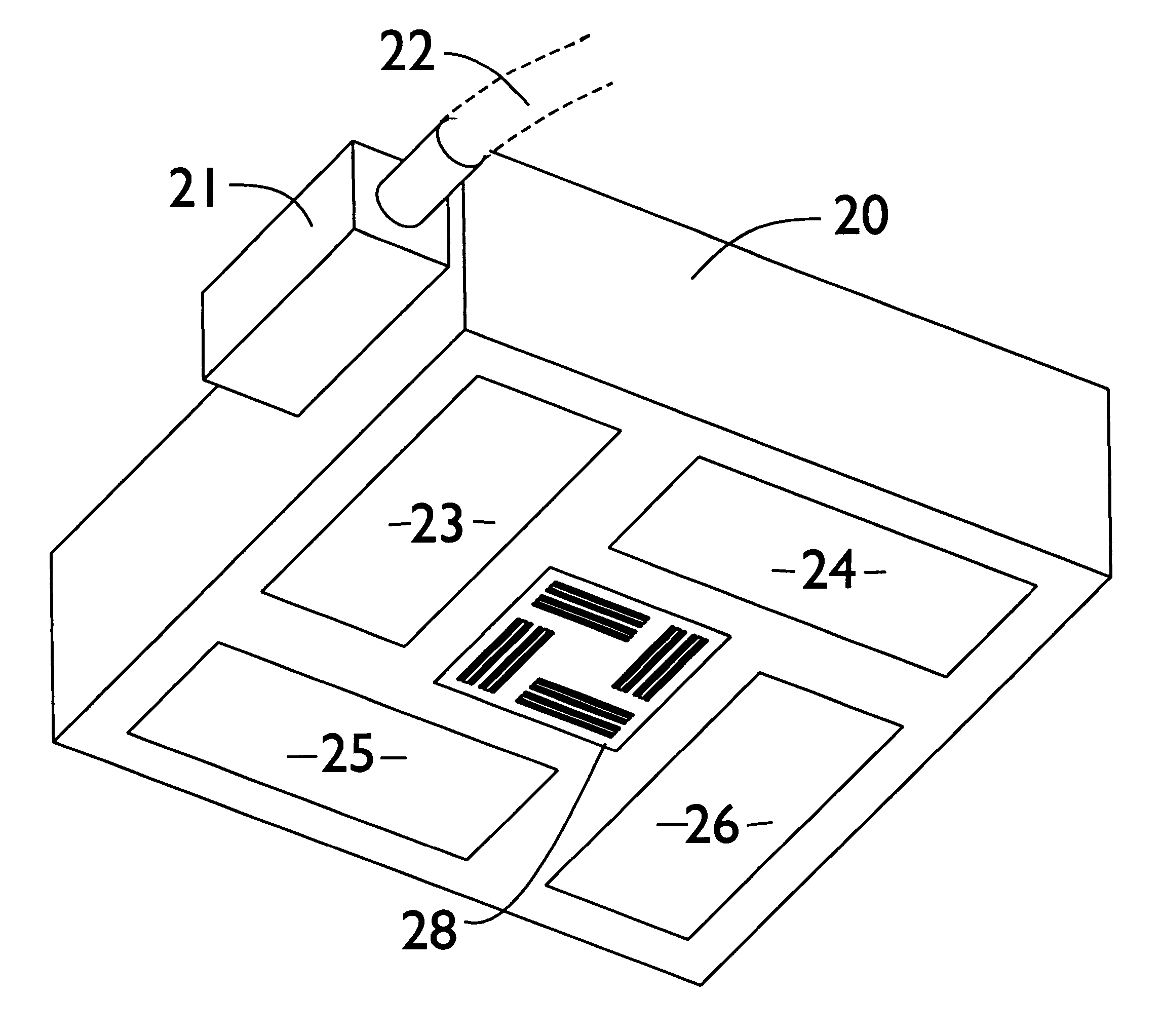
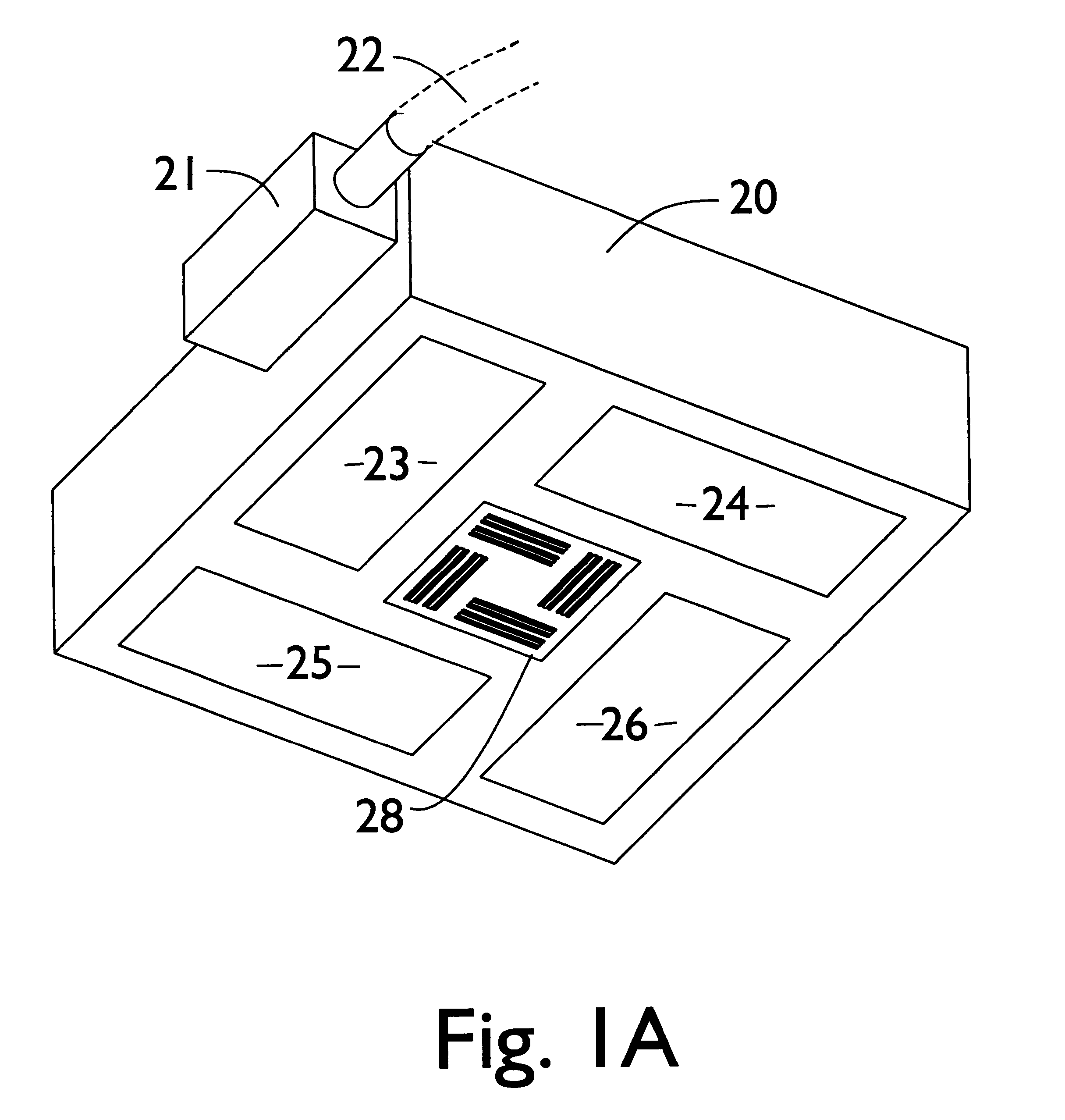
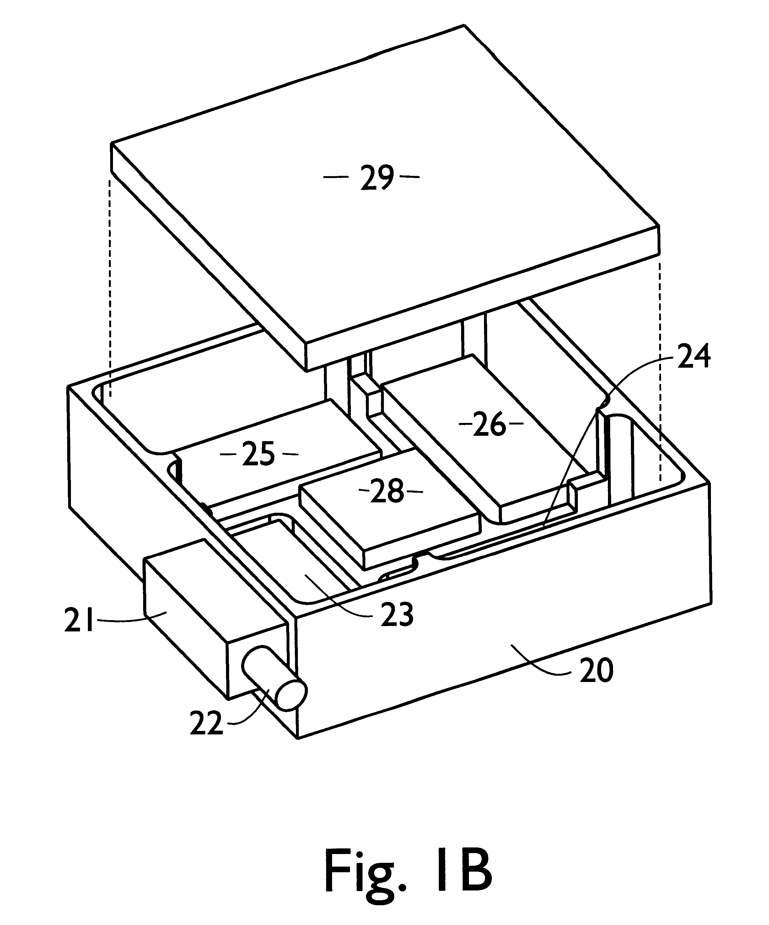
Referring to FIGS. 1A and 1B, there is an overall view of the closed-loop planar motor with integral AC magnetic position / orientation sensor.

FIG. 1A shows a bottom view of the hardware part of a preferred embodiment showing a nonmagnetic housing 20 whereon an electrical connector 21 is mounted. Flexible cable (or tether) 22 attached to connector 21 serves to conduct electrical signals to and from a computer, along with a supply of air for an air bearing surface comprised jointly of the bottom surfaces of housing 20 and elements 23-26 and 28. Toothed linear motor segments 23-26 provide electromotive force along directions parallel to the sides of housing 20. All of the elements 20-26 are well known in the art and together constitute what is commonly known as the moving part of a "planar linear motor," or "forcer" or "Sawyer" motor, after its inventor. We refer to the combination of a forcer and its platen (stator) simply as a planar motor. Planar motor ...


PUM


Abstract

The invention discloses a closed loop planar linear motor which includes a stationary stator (or platen) of arbitrary extent, and a moving forcer which is a single rigid body that can move over the planar stator surface on an air bearing with high speed and high precision in two orthogonal translational directions and a small rotation (or combinations thereof). An important distinguishing feature is a monolithic position and orientation sensor based on alternating current (AC) magnetic techniques which is an integral part of the forcer and occupies otherwise unused space in the forcer body. Also incorporated within the forcer is a special electronic processing element which converts weak AC signals from the sensor into usable high precision position and orientation information relative to the stator surface. A unique controller which is part of the closed-loop linear motor acts to combine information from the AC magnetic sensor with input from a user to provide precise, high-performance closed-loop control of the forcer, thereby enabling the forcer to be positioned with sub-micrometer precision and oriented with sub-millidegree precision on the stator surface. Additionally, owing to its closed-loop nature, the forcer can maintain its position and orientation even in the presence of disturbance forces and torques, and can emulate the operation of a mechanical spring and damper.

Description


Claims


Application Information

Patent Timeline
Owner RALPH L HOLLIS JR
Learn More