Fresnel lens sheet for rear projection screen

Inactive Publication Date: 2000-04-18
DAI NIPPON PRINTING CO LTD
View PDF5 Cites 40 Cited by
  • Summary
  • Abstract
  • Description
  • Claims
  • Application Information

AI Technical Summary

Problems solved by technology

If R>0.5 h, outer peripheral region of the Fresnel lens sheet 1 would have too short focal lengths, which increases loss of quantity of light and causes coloring.
If R>0.8 h, unbalanced loss of quantity of light would occur, causing coloring.

Method used


Image

  • Fresnel lens sheet for rear projection screen
  • Fresnel lens sheet for rear projection screen
  • Fresnel lens sheet for rear projection screen

Examples


example 2

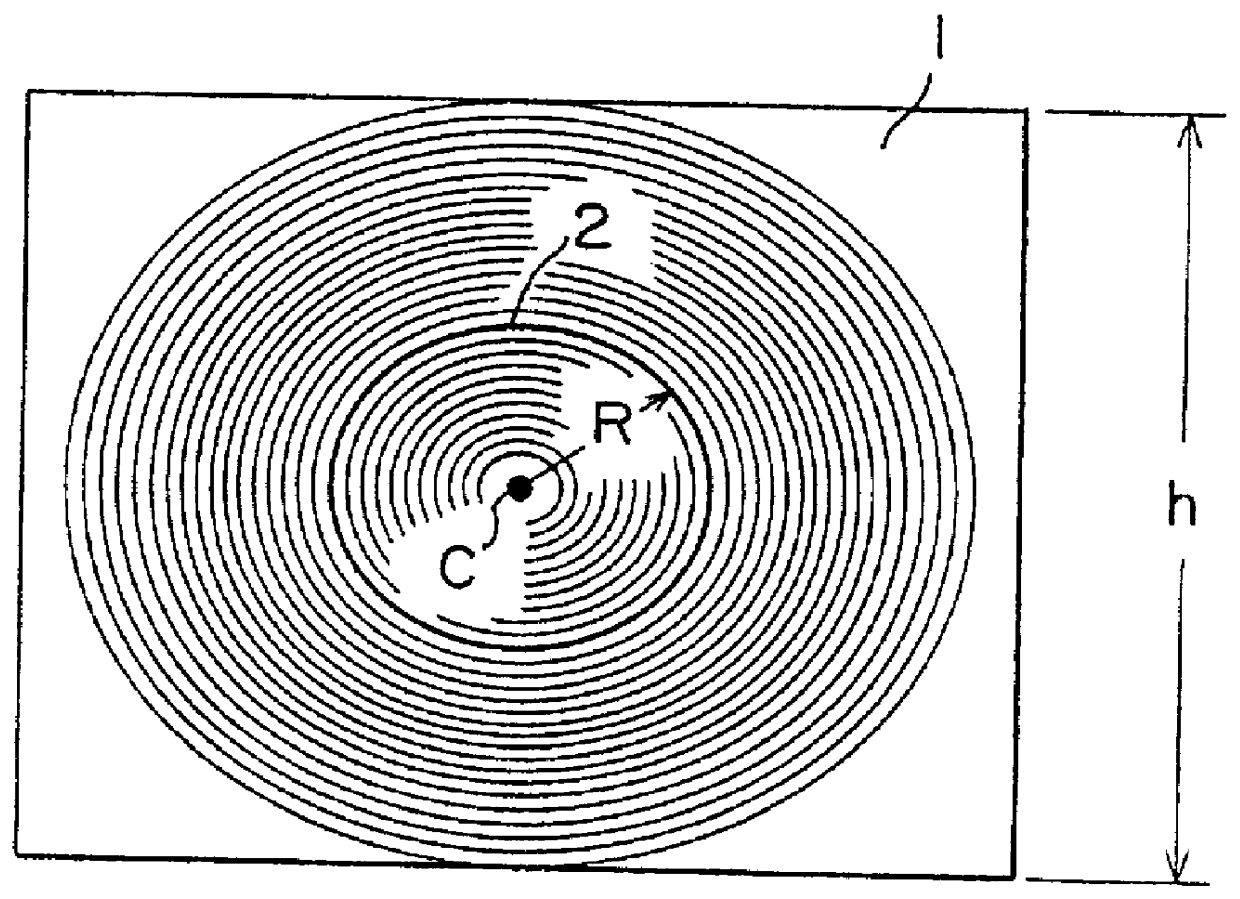
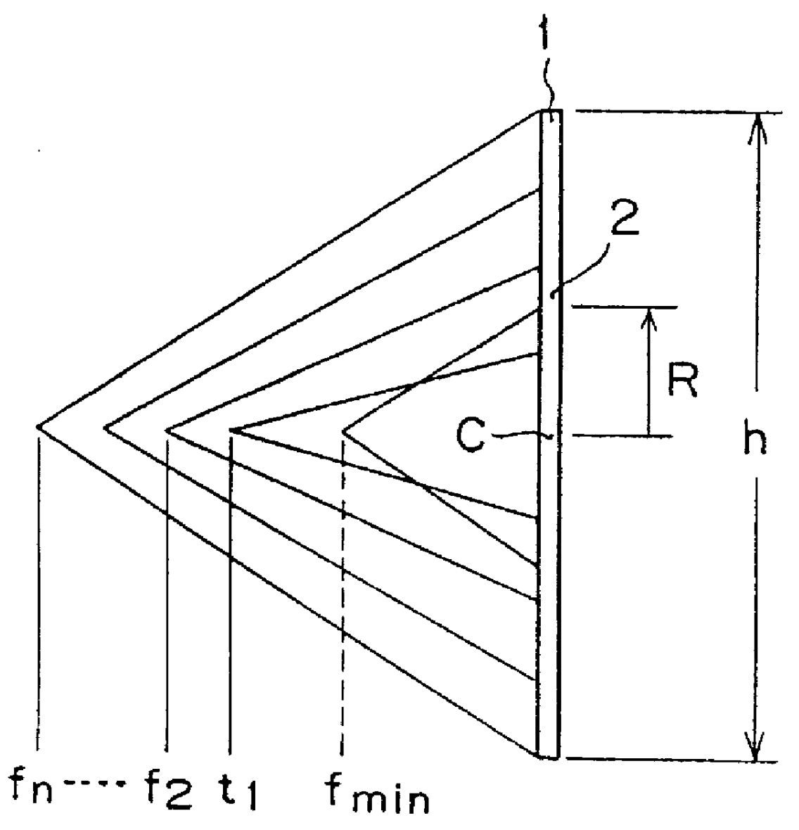
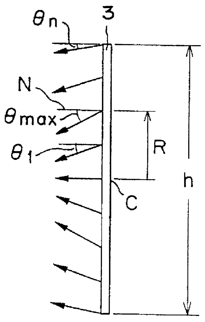
A Fresnel lens sheet having a .theta.-R characteristic as shown in FIG. 5 (.theta. is the exit angle) is Example 2 of the Fresnel lens sheet 2 of FIG. 3. The Fresnel lens sheet in Example 2 is 920 mm in height h and is intended for used in constructing a 60 in. screen for a television receiver of 940 mm in projection distance.

A rear projection screen was fabricated by combining the Fresnel lens sheet in Example 2 and a lenticular lens sheet, and the rear projection screen was incorporated into a rear projection television receiver for the sensory test of the performance of the rear projection screen. The rear projection screen had a peripheral portion of a satisfactory brightness and an excellent uniform brightness distribution.


PUM


Abstract

A Fresnel lens sheet of a multifocal type is intended to be used in combination with a lenticular lens sheet to construct a rear projection screen for a rear projection television receiver. An annular portion (2) of the Fresnel lens sheet at a distance (R) in a range of 0.05 h to 0.5 h, where h is the height of the Fresnel lens sheet, from the optical center (C) of the Fresnel lens sheet, have the shortest focal length fmin among those of other portions of the Fresnel lens sheet, whereby uniformity in brightness of a screen employing the Fresnel lens sheet can be achieved. Alternatively, a portion where an exit angle ( theta ) of outgoing light ray relative to a normal to the surface of the Fresnel lens sheet is the greatest, lies at a distance (R) in a range of 0.3 h to 0.8 h from the optical center (C) of the Fresnel lens sheet, to obtain the same result.

Description

1. Field of the InventionThe present invention relates to a Fresnel lens sheet to be employed in combination with a lenticular lens sheet in constructing a rear projection sheet for a rear projection television screen, and to a rear projection screen employing the Fresnel lens.2. Description of the Related ArtFresnel lens sheets are classified into those of a single-focal type which refract all light rays that have fallen thereon so as to collect at a single focus as shown in FIG. 6A, and those of a multifocal type which refract light rays that have fallen on regions near the periphery at focuses at longer focal lengths, and refract light rays that have fallen on regions near the center, at focuses at shorter focal lengths, respectively as shown in FIG. 6B. The center of a Fresnel lens is an optical center of the Fresnel lens where the lens angle at the lens top relative to a plane parallel to the major plane of the Fresnel lens, is nearly zero.When a rear projection screen employin...

Claims


Application Information

Patent Timeline
IPC IPC(8): G02B3/08G03B21/62G03B21/60G03B21/625
CPCG03B21/625G02B3/08G02B3/005G02B5/021
Inventor TAKAHASHI, KATSUNORI
Owner DAI NIPPON PRINTING CO LTD
Why Eureka
Try Eureka