Downhole wash tool

a technology for washing tools and downholes, applied in the direction of fluid removal, borehole/well accessories, sealing/packing, etc., can solve the problems of affecting the efficiency of over-all operation, large annulus between the tool and the cleaning fluid, and a substantial portion of the cleaning fluid not meeting the objective,

Inactive Publication Date: 2000-03-21
MOBIL OIL CORP
View PDF12 Cites 21 Cited by
  • Summary
  • Abstract
  • Description
  • Claims
  • Application Information

AI Technical Summary

Problems solved by technology

This requirement can result in a relatively large annulus between the tool and the inner wall of the liner when the tool is in an operable position within the liner.
Accordingly, when fluid flows out the nozzle during a cleaning operation, a substantial portion of that fluid will not achieve its objective, i.e. clean the openings and/or formation, but instead w

Method used


Image

  • Downhole wash tool
  • Downhole wash tool
  • Downhole wash tool

Examples


Embodiment Construction

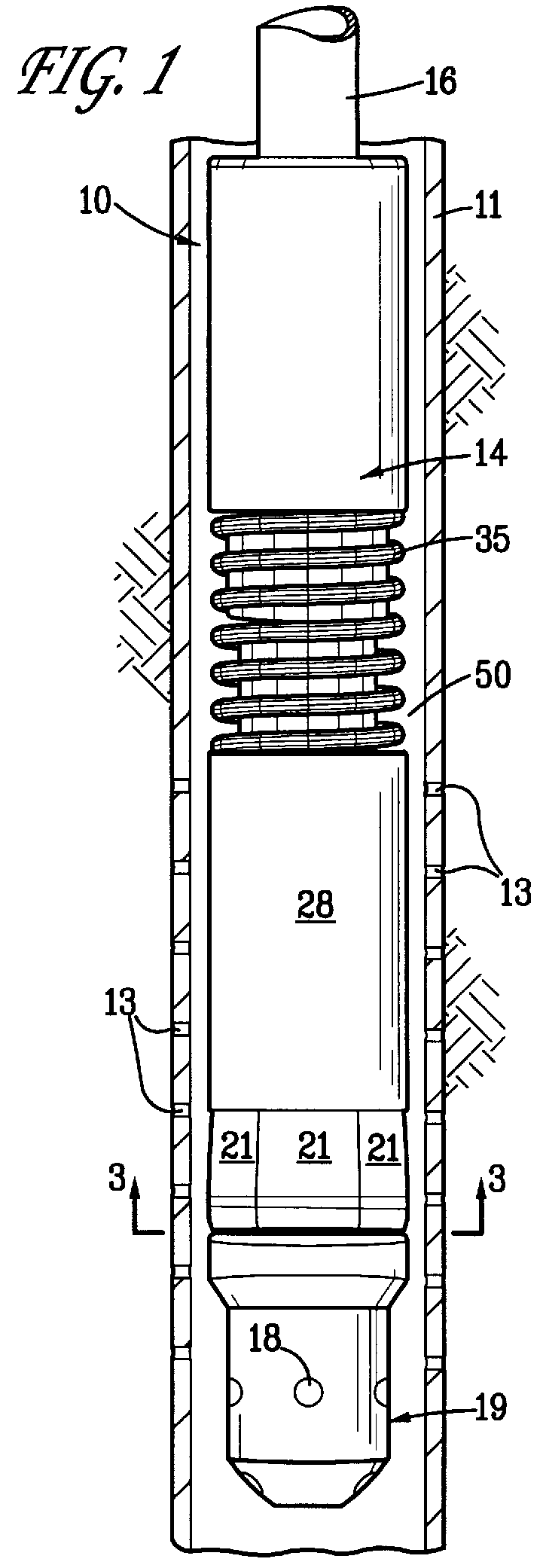
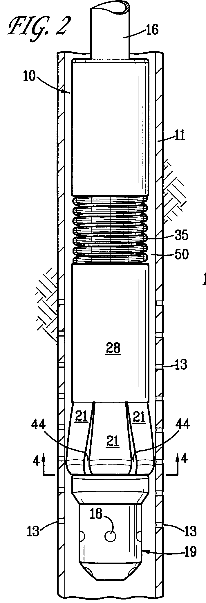
Referring more particularly to the drawings, FIG. 1 illustrates the downhole wash tool 10 of the present invention as it appears in a retracted position within a liner 11 which, in turn, is positioned within a borehole which has been drilled in formation 12. While the borehole may appear vertical in the FIGS., it should be recognized that the present tool is especially useful in inclined or horizontally-drilled wells as well as in vertical wells. Further, while the present invention is described in relation to a liner which is normally not cemented in a borehole, tool 10 can be used equally as well to inject fluid through openings in other well tubulars, e.g. perforations in cemented casing, etc.

Downhole wash tool 10 is comprised of a housing 14 which, as best seen in FIGS. 5 and 6, is preferably constructed of three elements 14a, 14b, 14c which, in turn, are then joined together by any appropriate means (e.g. threads, not shown). The upper housing element 14a includes a connector 1...


PUM


Abstract

A downhole wash tool for carrying out cleaning operations in a borehole. The tool has a housing on which a plurality of flow-blocking, diverters (e.g. steel) are mounted. The diverters move between a retracted position and an extended position wherein the diverters effectively block flow around the tool. A retainer normally maintains the diverters in their retracted position when in a first position and releases the diverters when in a second position. A spring normally biases the retainer towards its first position. The retainer is hydraulically-actuated through the housing to move it towards its second position. When the cleaning operation is completed, pressure in the workstring is relaxed whereupon the spring moves the retainer back to its first position to retract the diverters.

Description

1. TECHNICAL FIELDThe present invention relates to a downhole wash tool and in one of its aspects relates to a downhole wash tool for cleaning openings in a well tubular and / or the formation therebehind wherein said tool has flow-blocking diverters thereon which are normally retracted to allow the tool to be run in and out of the borehole but expand outwardly during a wash operation to substantially block upward flow of the wash fluid around the tool when the tool is in an operable position within a wellbore.2. BACKGROUND OF THE INVENTIONIn producing hydrocarbons or the like from subterranean formations, it is now common to use boreholes or laterals which extend horizontally into the producing formation. Such horizontal boreholes are often completed by "casing" the borehole with a liner having pre-formed openings therein (e.g. perforations, slots, etc.). This uncemented liner serves (a) to stabilize the formation and prevent caving of the borehole during production and (b) to provid...

Claims


Application Information

Patent Timeline
IPC IPC(8): E21B37/00E21B37/08
CPCE21B37/08
Inventor MUELLER, MANFRED W.
Owner MOBIL OIL CORP
Why Eureka
Try Eureka