Acoustic wave device, and ladder filter including the same

Pending Publication Date: 2022-11-10
MURATA MFG CO LTD
View PDF0 Cites 0 Cited by
  • Summary
  • Abstract
  • Description
  • Claims
  • Application Information

AI Technical Summary

Benefits of technology

The present invention provides an acoustic wave device with multiple resonators that can be smaller in size without affecting their frequency characteristics. This is achieved by using a shared reflector that is a reflector for both resonators, which has a narrow stop band that prevents signals from one resonator from interfering with signals from the other resonators. This results in improved signal quality and reduced device size.

Problems solved by technology

However, depending on the configuration of the device, the frequency characteristics of adjacent surface acoustic wave resonators are different from each other, so just simply sharing the reflector may lead to a decrease in the frequency characteristics of the overall device on the contrary, and desired characteristics are possibly not able to be implemented.

Method used


Image

  • Acoustic wave device, and ladder filter including the same
  • Acoustic wave device, and ladder filter including the same
  • Acoustic wave device, and ladder filter including the same

Examples


first preferred embodiment

Configuration of Filter Device

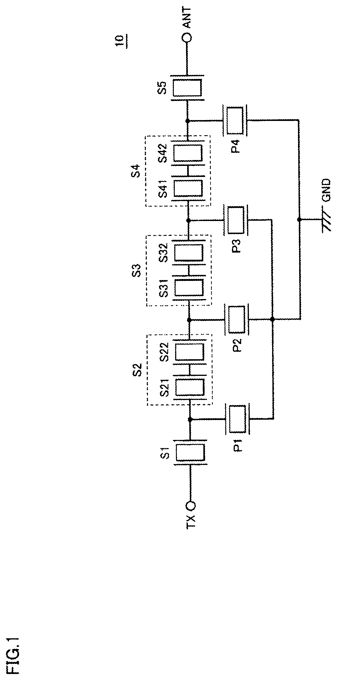
[0030]FIG. 1 is a diagram showing the circuit configuration of a filter device 10 including acoustic wave devices according to a first preferred embodiment. The filter device 10 is a filter device preferably for use in a transmission circuit of a communication device and is a ladder filter connected between a transmission terminal TX and an antenna terminal ANT, for example. The filter device 10 filters a signal received at the transmission terminal TX and outputs the signal from the antenna terminal ANT.

[0031]The filter device 10 includes series arm resonant portions S1 to S5 connected in series between the transmission terminal TX and the antenna terminal ANT, and parallel arm resonant portions P1 to P4. Each of the series arm resonant portions S1 to S5 and the parallel arm resonant portions P1 to P4 includes at least one acoustic wave resonator. In the example of FIG. 1, each of the series arm resonant portions S1, S5 and the parallel arm resonant po...

first modification

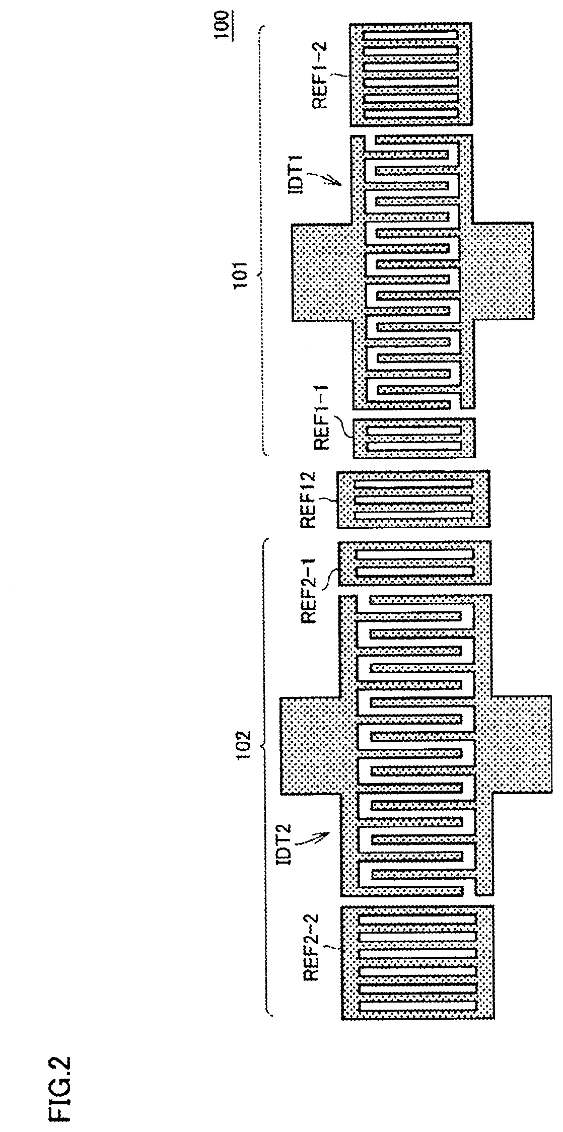
[0075]In the acoustic wave device 100 of the first preferred embodiment shown in FIG. 2, the configuration in which two acoustic wave resonators disposed adjacent to each other are disposed such that the centers of the propagation directions of surface acoustic waves coincide with each other, that is, the directions passing through the center of the overlap width of the interdigital transducer electrode and orthogonal to the electrode fingers coincide with each other has been described. However, the centers of the propagation directions of surface acoustic waves in two acoustic wave resonators may be different from each other.

[0076]FIG. 11 is a top view of an acoustic wave device 100A according to a first modification. The acoustic wave device 100A includes acoustic wave resonators 101A, 102A having a similar configuration to those of FIG. 2, and a shared reflector REF12A disposed between the acoustic wave resonators 101A, 102A. The acoustic wave resonator 101A includes an interdigi...

second modification

[0081]In the acoustic wave devices of the first preferred embodiment and the first modification, the configuration in which the electrode fingers in each of the interdigital transducer electrode and the reflectors extend in the direction orthogonal to the busbars connected to the electrode fingers has been described. In an acoustic wave device of a second modification, the configuration in which the electrode fingers of each of an interdigital transducer electrode and reflectors are disposed obliquely with respect to busbars will be described.

[0082]FIG. 12 is a top view of an acoustic wave device 100B according to the second modification. The acoustic wave device 100B includes acoustic wave resonators101B, 102B, and a shared reflector REF12B disposed between the acoustic wave resonators 101B, 102B. As in the case of the first modification, the acoustic wave resonator 101B and the acoustic wave resonator 102B are disposed at offset positions.

[0083]The acoustic wave resonator 101B inc...


PUM


Abstract

An acoustic wave device includes a substrate including a piezoelectric layer, first and second resonators on the substrate, and a shared reflector. The second resonator is located on the substrate adjacent to the first resonator and has different frequency characteristics than the first resonator. The shared reflector is located on the substrate between the first resonator and the second resonator and is a reflector for both the first resonator and the second resonator. The first resonator includes a first interdigital transducer electrode with electrode fingers positioned with a first pitch. The second resonator includes a second interdigital transducer electrode with electrode fingers positioned with a second pitch. A lower limit frequency of a stop band of the shared reflector is between a lower limit frequency of a stop band of the first resonator and a lower limit frequency of a stop band of the second resonator. An upper limit frequency of the stop band of the shared reflector is between an upper limit frequency of the stop band of the first resonator and an upper limit frequency of the stop band of the second resonator.

Description

CROSS REFERENCE TO RELATED APPLICATIONS[0001]This application claims the benefit of priority to Japanese Patent Application No. 2020-015067 filed on Jan. 31, 2020 and is a Continuation Application of PCT Application No. PCT / JP2021 / 003252 filed on Jan. 29, 2021. The entire contents of each application are hereby incorporated herein by reference.BACKGROUND OF THE INVENTION1. Field of the Invention[0002]The present disclosure relates to an acoustic wave device and a ladder filter including the same and, more specifically, to a technology for reducing the size of an acoustic wave device.2. Description of the Related Art[0003]Japanese Unexamined Patent Application Publication No. 10-303691 describes a filter device made up of a plurality of surface acoustic wave (SAW) resonators. Generally, in such a filter device, to reduce leakage of signals, to be propagated through the surface acoustic wave resonators, from the resonators, reflectors are disposed on both sides of an interdigital tran...

Claims


Application Information

Patent Timeline
IPC IPC(8): H03H9/56H03H9/145H03H9/02
CPCH03H9/568H03H9/14541H03H9/02992H03H9/02771H03H9/02574H03H9/6483H03H9/14547H03H9/02842
Inventor NAKAMURA, KENTARO
Owner MURATA MFG CO LTD
Why Eureka
Try Eureka