Ventilation system comprising at least one ventilator and at least one diagnosis device and method of operating

a ventilation system and ventilator technology, applied in the field of ventilators, can solve the problems of significant effort, synchronization of data detected in the context of therapy supervision, and patients' frequent visits to sleep laboratory,

Pending Publication Date: 2022-11-03
LOWENSTEIN MEDICAL TECH SA
View PDF0 Cites 0 Cited by
  • Summary
  • Abstract
  • Description
  • Claims
  • Application Information

AI Technical Summary

Benefits of technology

The ventilation system in this patent offers several advantages. It uses a synchronization unit to automatically find signal changes caused by triggers, such as simultaneous events. This allows for comfortable therapy supervision at home and reduces effort and costs. The system is easy to operate and accurately synchronizes. Additionally, it allows for deliberate manipulation of the respiratory gas flow, resulting in identifiable signal changes and reliable synchronization.

Problems solved by technology

However, such a synchronization of the data detected in the context of the therapy supervision is linked to significant effort.
However, visiting a sleep laboratory often represents an exhausting and unpleasant effort for the patient.
Moreover, the data obtained in the sleep laboratory sometimes do not reflect the actual ventilation situation of the patient due to the unfamiliar sleep situation.
However, this has proven to be inadequate for automated synchronization, since the internal clocks of ventilator and diagnostic device generally do not run sufficiently synchronously or an interfering speed difference results during the recording.

Method used


Image

  • Ventilation system comprising at least one ventilator and at least one diagnosis device and method of operating
  • Ventilation system comprising at least one ventilator and at least one diagnosis device and method of operating
  • Ventilation system comprising at least one ventilator and at least one diagnosis device and method of operating

Examples


Embodiment Construction

[0068]The particulars shown herein are by way of example and for purposes of illustrative discussion of the embodiments of the present invention only and are presented in the cause of providing what is believed to be the most useful and readily understood description of the principles and conceptual aspects of the present invention. In this regard, no attempt is made to show details of the present invention in more detail than is necessary for the fundamental understanding of the present invention, the description in combination with the drawings making apparent to those of skill in the art how the several forms of the present invention may be embodied in practice.

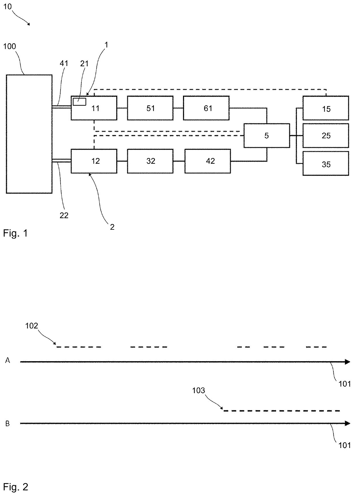
[0069]FIG. 1 shows a ventilation system 10 according to the invention having a ventilator 1 and a diagnostic device 2 coupled to the ventilator 1. The ventilation system 10 is operated according to the method according to the invention. The ventilator 1 has a ventilation unit 11, which generates a respiratory gas flow by m...


PUM


Abstract

Ventilation system (having a ventilator and having a diagnostic device, wherein the ventilator comprises a ventilation unit for generating a respiratory gas flow for ventilation and a detection unit (for detecting a ventilation signal characteristic for the respiratory gas flow over time. The diagnostic device comprises a sensor unit for detecting a diagnostic signal over time. The synchronization unit is operationally connected to the detection unit and the sensor unit and is suitable and configured for studying a time curve of the ventilation signal and a time curve of the diagnostic signal respectively for a signal change caused by the same event and bringing the curve of the ventilation signal and the curve of the diagnostic signal into chronological correspondence so that the event occurs simultaneously in both signal curves.

Description

CROSS-REFERENCE TO RELATED APPLICATIONS[0001]The present application claims priority under 35 U.S.C. § 119 of German Patent Application No. 102021111291.5, filed Apr. 30, 2021, the entire disclosure of which is expressly incorporated by reference herein.BACKGROUND OF THE INVENTION1. Field of the Invention[0002]The present invention relates to a ventilation system having at least one ventilator and having at least one diagnostic device and a method for operating such a ventilation system. The ventilator comprises at least one ventilation unit for generating a respiratory gas flow for a ventilation and at least one detection unit for detecting at least one ventilation signal characteristic of the respiratory gas flow over time. The diagnostic device comprises at least one sensor unit for detecting at least one diagnostic signal over time.2. Discussion of Background Information[0003]Such ventilation systems are typically used for therapy supervision. In general, the patient uses the ve...

Claims


Application Information

Patent Timeline
Patent Type & Authority Applications(United States)
IPC IPC(8): A61M16/00A61B5/087
CPCA61M16/024A61M16/0051A61B5/087A61M2016/0027A61M2016/0036A61M2016/0033A61M2205/15A61M2230/205A61M2230/04A61M2230/60A61M2230/40A61M2230/30A61M2230/50A61M2205/3375A61M2205/3592A61M2205/3334A61M2205/3344A61M2205/502A61M2209/088A61M16/16A61M16/125A61M16/14A61M16/1005A61M2205/52A61M2230/62A61M2205/332A61M2205/3306A61M2205/3561A61M16/0003A61M16/026A61B5/6803A61B2505/01A61B5/7267A61B5/743A61B5/7282A61B5/4836A61B5/7246A61B5/7221A61B2562/0247A61B2562/0271A61B5/0077A61B5/015A61B5/0823A61B5/4818A61B5/0507A61B5/0535A61B2562/0204A61B2562/0219A61B5/021A61B5/14542A61B5/318A61B5/389
Inventor SCHWAIBOLD, MATTHIASVERHOEVEN, JANFURTHMUELLER, JOCHEN
Owner LOWENSTEIN MEDICAL TECH SA
Why Eureka
Try Eureka