
Autostereoscopic Head-Up Display Device Using Two Directional Backlit Displays

Pending Publication Date: 2022-10-27
E LEAD ELECTRONICS
View PDF0 Cites 0 Cited by
  • Summary
  • Abstract
  • Description
  • Claims
  • Application Information

AI Technical Summary

Benefits of technology

The present invention provides an auto-stereoscopic head-up display device using two directional backlit displays. This device can prevent light leakage and crosstalk caused by poor isolation of light paths, by allowing the single eye box to cover only a single eye. The design of staggered light paths also enhances the isolation between the light paths, resulting in improved display quality.

Problems solved by technology

However, the DLP projection display has a complex structure, high cost, and large volume, and if it has the same resolution as the LCD screen, the price of DLP projection display is even more expensive.
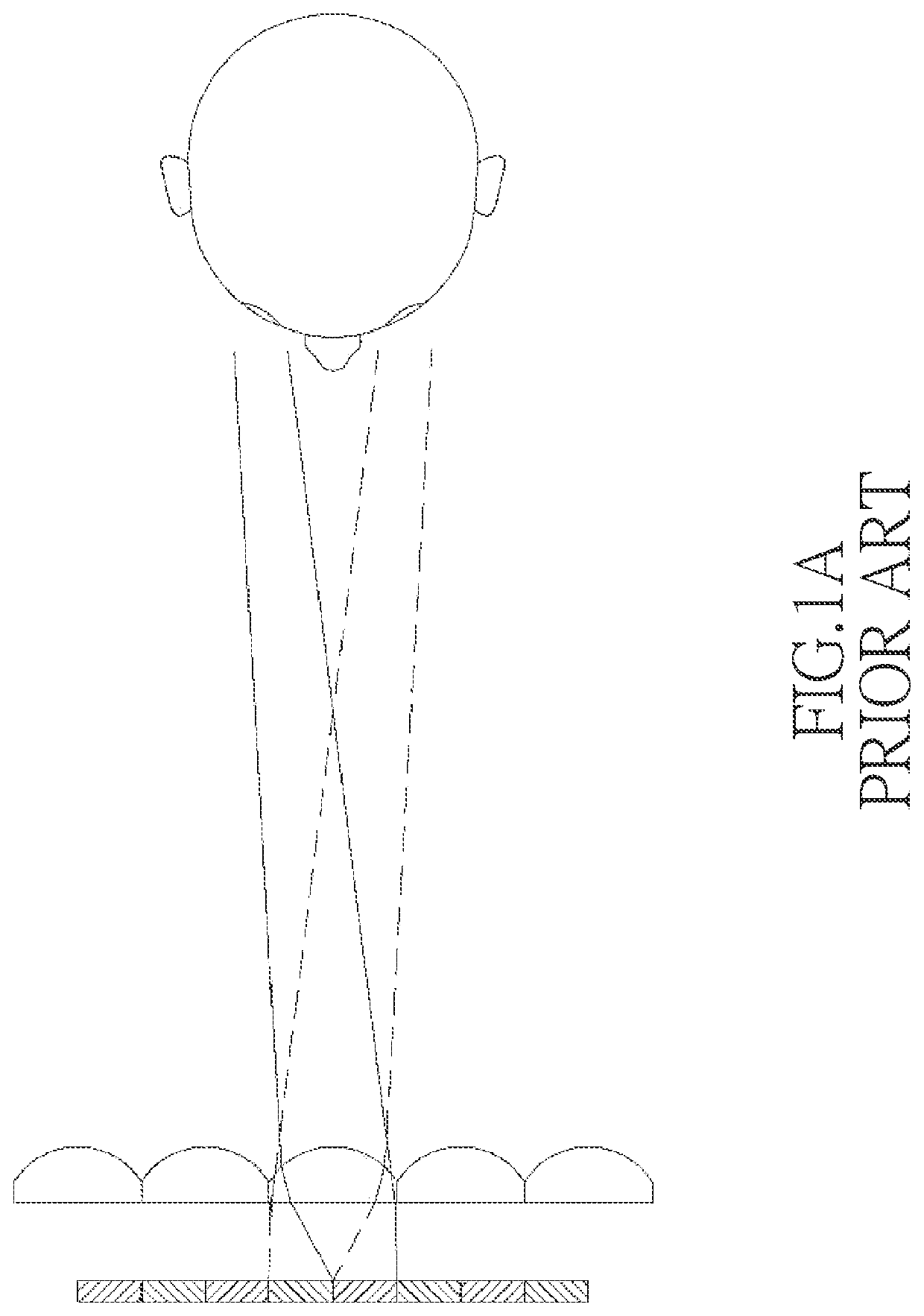
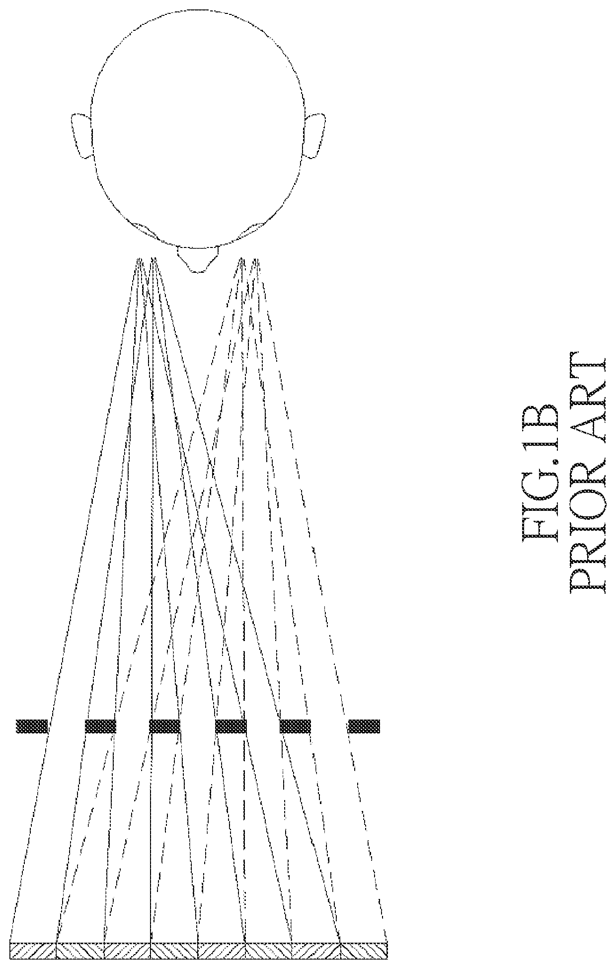
Both the lenticular lens type and the parallax barrier type need to divide the image information into equidistant vertical strips, and then display the left-eye images and the right-eye images in an interleaved manner, which results in the disadvantage of halving the horizontal resolution.
Furthermore, the alignment accuracy between the pixels on the liquid crystal panel is extremely demanding, so the problem of poor separation of images for the left and right eyes is likely to occur.
Moreover, the parallax barrier technology has the disadvantage of halving the brightness.
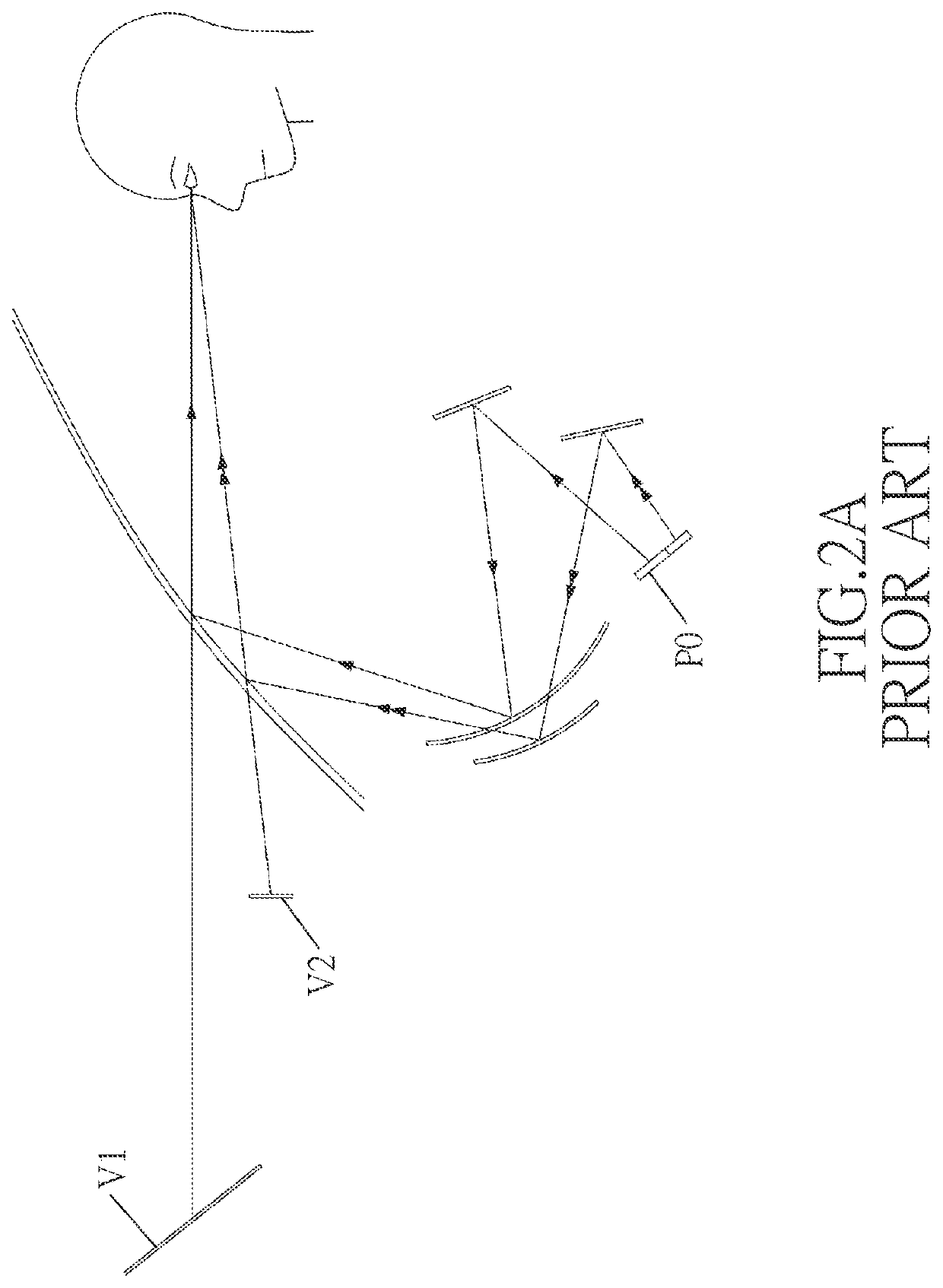
However, the optical design of this stereoscopic image will cause the eye box to be too large due to the wide viewing angles of the LCD P1 and P2, and cause the poor isolation between the two approximately parallel light paths resulting in light leakage and cross talk problems, which seriously affects the visual quality of viewing.

Method used


Image

  • Autostereoscopic Head-Up Display Device Using Two Directional Backlit Displays
  • Autostereoscopic Head-Up Display Device Using Two Directional Backlit Displays
  • Autostereoscopic Head-Up Display Device Using Two Directional Backlit Displays

Examples


Embodiment Construction

[0044]Please refer to FIG. 5, where an embodiment of the present invention provides an autostereoscopic head-up display device using two directional backlit displays, and the head-up display device includes a first directional backlit display 11, a second directional backlit display 12, a first reflector 21, a second reflector 22, a beam splitter 31 and a third reflector 32. The positions of these elements in the arrangement can be, for example, as shown in FIG. 5, where the beam splitter 31 is located between the first directional backlit display 11, the second directional backlit display 12 and the third reflector 32.

[0045]The first directional backlit display 11 is used to provide (i.e., emit or project) a first image light beam IM1 with directivity. The second directional backlit display 12 is used to provide (i.e., emit or project) a second image light beam IM2 with directivity. The first image light beam IM1 and the second image light beam IM2 are parallax image light beams to...


PUM


Abstract

An autostereoscopic head-up display device includes two directional backlit type displays, a first reflector, a second reflector, a third reflector and a beam splitter. The two displays emit two image light beams with directivity, respectively, and the two image light beams are parallax image light for a viewer's eyes. One of the two displays, the first reflector, the beam splitter, the windshield and one of the viewer's eyes form a first light path, and the other one of the two displays, the second reflector, the beam splitter, the third reflector, the windshield and the other one of the viewer's eyes form a second light path. The two image light beams are projected onto the viewer's eyes through the first and second light paths, to form a stereoscopic image.

Description

BACKGROUNDField of the Invention[0001]The present invention relates to a head-up display, and more particularly to an autostereoscopic head-up display device using two directional backlit displays.Description of Related Art[0002]In the conventional head-up display technology, the digital light processing (DLP) projection display of the reflective display or the thin film transistor liquid crystal display (TFT-LCD) of the backlit display can be used. However, the DLP projection display has a complex structure, high cost, and large volume, and if it has the same resolution as the LCD screen, the price of DLP projection display is even more expensive. Therefore, the LCD screen is a better choice when considering small size, low cost, high contrast and high resolution.[0003]Common autostereoscopic technologies that use liquid crystal displays can be divided into the use of lenticular lenses and the use of parallax barriers. As shown in FIG. 1A, the lenticular lens type uses the focusing...

Claims


Application Information

Patent Timeline
IPC IPC(8): G02B30/33G02B27/01
CPCG02B30/33G02B27/0101G02B2027/0134G02B27/14G02B27/283
Inventor CHEN, STEPHEN
Owner E LEAD ELECTRONICS
Learn More