Screw compressor
a screw compressor and screw technology, applied in the direction of liquid fuel engines, rotary/oscillating piston pump components, machines/engines, etc., can solve the problems of reduced energy-saving performance of compressors, limited liquid feed port installation range, etc., to expand the installable range of liquid feed mechanisms.
- Summary
- Abstract
- Description
- Claims
- Application Information
AI Technical Summary
Benefits of technology
Problems solved by technology
Method used
Image
Examples
first embodiment
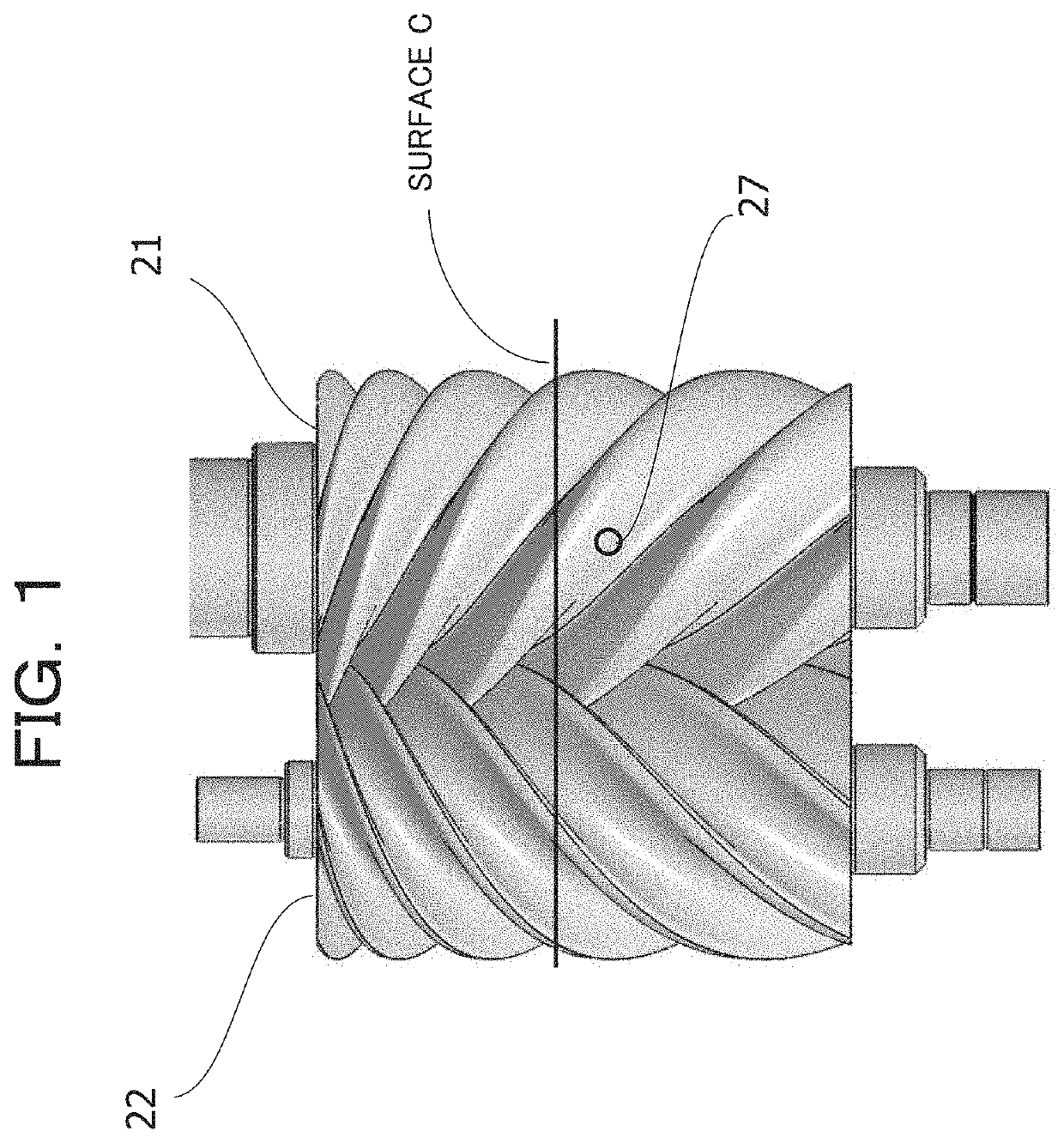
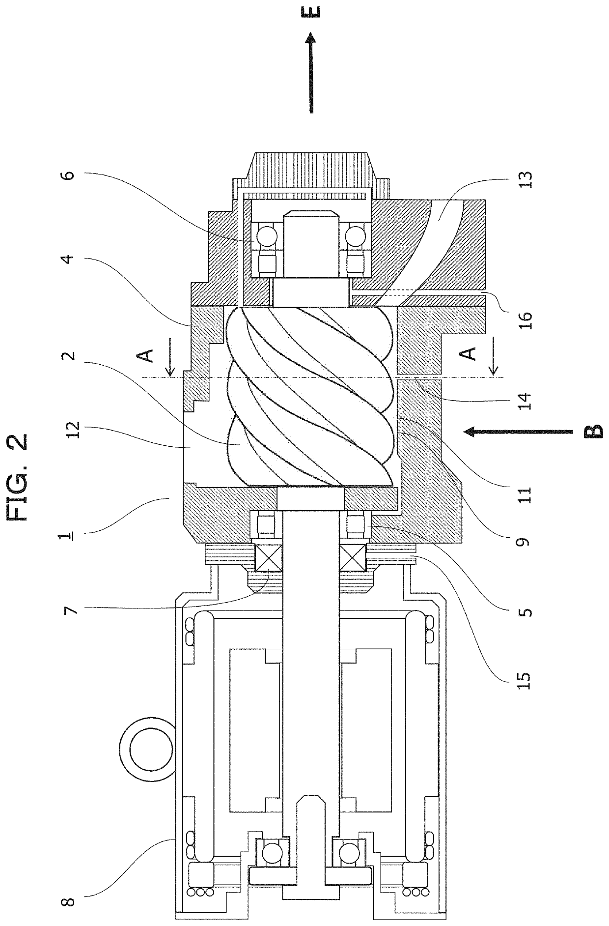
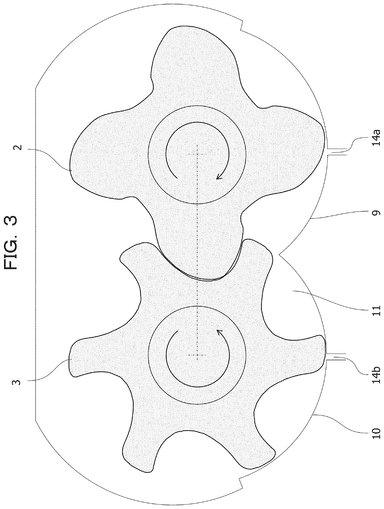
[0041]A first embodiment will be described with reference to FIGS. 1, 2, 3, 5, 6, and 15. Further, this embodiment relates to a liquid feed type screw air compressor. In the description of this embodiment, the same parts as described above will be described with the same reference numerals.
[0042]In this embodiment, the male screw rotor 2 and the female screw rotor 3 shown in FIG. 3 are respectively a male screw rotor 21 having a changing pitch and a female screw rotor 22 having a changing pitch shown in FIG. 1 and a drill hole liquid feed port 27 is installed on the discharge end surface side in relation to the surface C shown in FIG. 1. The male screw rotor 21 having a changing pitch and the female screw rotor 22 having a changing pitch are screw rotors whose pitches increase from the suction end surface toward the discharge end surface, that is, in the axial direction of the screw rotor.
[0043]FIG. 5(a) is a diagram showing the male screw rotor 21 having a changing pitch and the fe...
second embodiment
[0064]A second embodiment will be described with reference to FIGS. 3, 7, 8, 9, and 10. Additionally, this embodiment relates to the liquid feed type screw compressor similarly to the first embodiment and the same parts as in the first embodiment will be described with the same reference numerals.
[0065]In this embodiment, the male screw rotor 2 and the female screw rotor 3 shown in FIG. 3 are respectively the male screw rotor 21 having a changing pitch and the female screw rotor 22 having a changing pitch and a jet collision nozzle 28 is installed on the discharge end surface side in relation to the surface C as shown in FIG. 7.
[0066]The jet collision nozzle will be described with reference to FIG. 8. FIG. 8 shows a cross-sectional view of the jet collision nozzle. A first injection port 29 and a second injection port 30 having an opening diameter smaller than that of the liquid feed port 14 are connected to the end portion of the liquid feed port 14 while being inclined by an angle...
third embodiment
[0075]A configuration of this embodiment will be described with reference to FIGS. 2, 3, 11, 13, and 16. Further, the same parts as described above will be described with the same reference numerals.
[0076]In this embodiment, the male screw rotor 2 and the female screw rotor 3 shown in FIG. 3 are respectively a male screw rotor 32 having a changing pitch and a female screw rotor 33 having a changing pitch shown in FIG. 13 and the drill hole liquid feed port 27 is installed on the suction end surface side in relation to the surface D shown in FIG. 13.
[0077]The male screw rotor 32 having a changing pitch and the female screw rotor 33 having a changing pitch are the screw rotors having a pitch decreasing from the suction end surface toward the discharge end surface.
[0078]FIG. 11(a) shows the male screw rotor 32 having a changing pitch and the female screw rotor 33 having a changing pitch in the direction B of FIG. 2, where the upper side of FIG. 11 is the suction end surface and the low...
PUM
 Abstract
Description
Claims
Application Information
 - R&D
- Intellectual Property
- Life Sciences
- Materials
- Tech Scout
- Unparalleled Data Quality
- Higher Quality Content
- 60% Fewer Hallucinations
Browse by: Latest US Patents, China's latest patents, Technical Efficacy Thesaurus, Application Domain, Technology Topic, Popular Technical Reports.
© 2025 PatSnap. All rights reserved.Legal|Privacy policy|Modern Slavery Act Transparency Statement|Sitemap|About US| Contact US: help@patsnap.com


