
Support component, housing structure, and equipment

Pending Publication Date: 2022-09-29
FUJIFILM BUSINESS INNOVATION CORP
View PDF7 Cites 0 Cited by
  • Summary
  • Abstract
  • Description
  • Claims
  • Application Information

AI Technical Summary

Benefits of technology

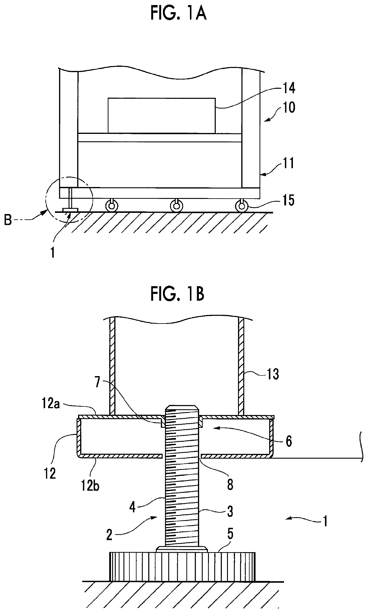
This patent is about a new way to install equipment using a support component. This component includes a leg component with a male thread and a pedestal, and a receiving component with an extruded portion and a through-hole. This design allows for easy adjustment of the equipment's height, and ensures that the leg component remains strong and secure compared to previous versions without the receiving component.

Problems solved by technology

Regarding a support component used in the related art to install an equipment, the component cost and the number of operations are increased due to welding of a nut that receives a leg component for height adjustment.
In addition, it is difficult to maintain the supporting strength for the leg component without using a welding nut.
However, aspects of the non-limiting embodiments are not required to overcome the disadvantages described above, and aspects of the non-limiting embodiments of the present disclosure may not overcome any of the disadvantages described above.

Method used


Image

  • Support component, housing structure, and equipment
  • Support component, housing structure, and equipment
  • Support component, housing structure, and equipment

Examples


first exemplary embodiment

[0046]Overall Configuration of Image Forming Apparatus

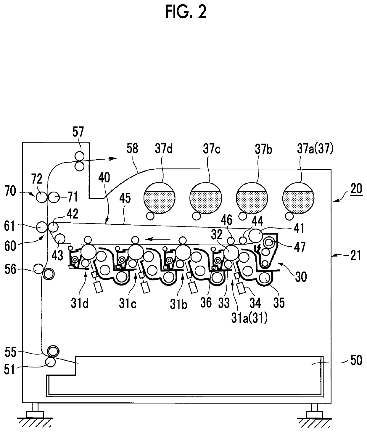
[0047]FIG. 2 is an explanatory view showing an overall configuration of an image forming apparatus as an equipment according to a first exemplary embodiment.

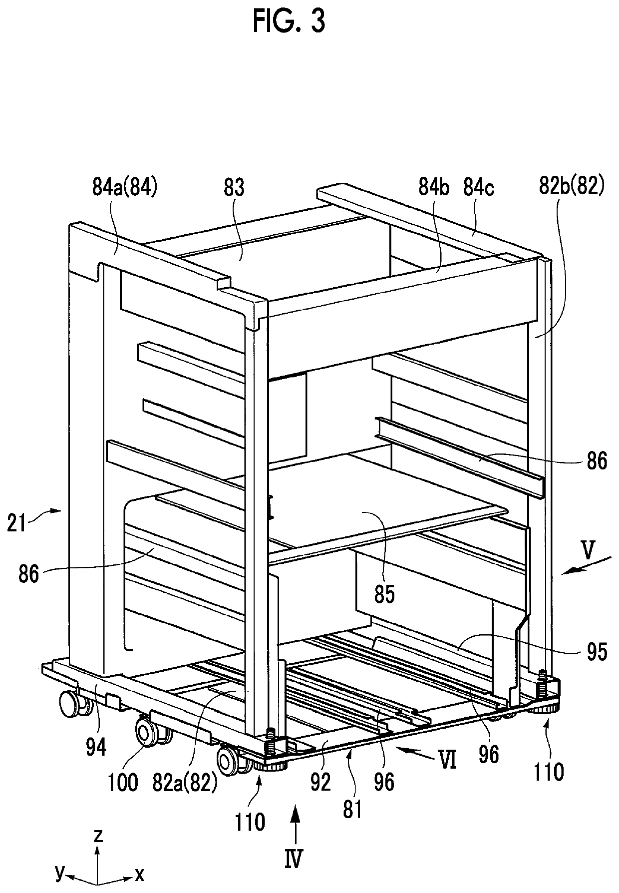
[0048]It should be noted that the image forming apparatus shown in FIG. 2 schematically shows one configuration example, and is not directly assembled into an apparatus housing shown in FIGS. 3 to 6.

[0049]In the figure, in an image forming apparatus 20, an image forming engine 30 that forms an image of a plurality of colors (four colors of yellow, magenta, cyan, and black in the present exemplary embodiment) is mounted in an apparatus housing 21, a recording material supply device 50 in which a recording material such as sheets is stored is arranged below the image forming engine 30, and a recording material transport path 55 from the recording material supply device 50 is arranged in a substantially vertical direction.

[0050]In this example, in the image forming engine 30, im...


PUM


Abstract

A support component includes a leg component having a male thread portion that is provided on at least an upper side of a rod extending in a height direction, and a pedestal portion that is provided larger than the rod and provided at a lower end portion of the rod, and a receiving component having a extruded portion that is provided, in a frame material including two vertically separated plate materials constituting a housing bottom portion of an equipment, in the plate material located on an upper side of the frame material and into which the male thread portion of the rod is screwed, and a through-hole that is provided in the plate material located on a lower side of the frame material and through which the rod passes, in which the support component enables height adjustment in a state in which the rod of the leg component is inserted through the extruded portion and the through-hole of the receiving component.

Description

CROSS-REFERENCE TO RELATED APPLICATIONS[0001]This application is based on and claims priority under 35 USC 119 from Japanese Patent Application No. 2021-055146 filed Mar. 29, 2021.BACKGROUND(i) Technical Field[0002]The present invention relates to a support component used for installing an equipment, a housing structure, and an equipment.(ii) Related Art[0003]In installing an equipment such as a multifunction device, a home appliance, and furniture, a support component may be used as a leg for height adjustment and leveling of the equipment.[0004]As this kind of support component, for example, forms described in JP1999-172218A and JP1996-275959A are already known.[0005]JP1999-172218A discloses a form in which a guide mechanism that guides a shaft that slides through a plate-shaped body is constituted by a through-hole formed in the plate-shaped body and a tubular portion integrally protruding in an axial direction of the shaft so as to surround the circumference of the through-hole,...

Claims


Application Information

Patent Timeline
IPC IPC(8): F16M7/00G03G21/16
CPCF16M7/00G03G21/1604G03G2215/00004F16M3/00H05K5/0234A47B91/024F16M11/24D06F39/125A47B91/022
Inventor SURUGA, MISAKICHIBA, NAOTO
Owner FUJIFILM BUSINESS INNOVATION CORP
Learn More