
Device and method for acquiring multi-luminosity images

Pending Publication Date: 2022-09-08
KYUNGPOOK NAT UNIV IND ACADEMIC COOP FOUND
View PDF0 Cites 1 Cited by
  • Summary
  • Abstract
  • Description
  • Claims
  • Application Information

AI Technical Summary

Benefits of technology

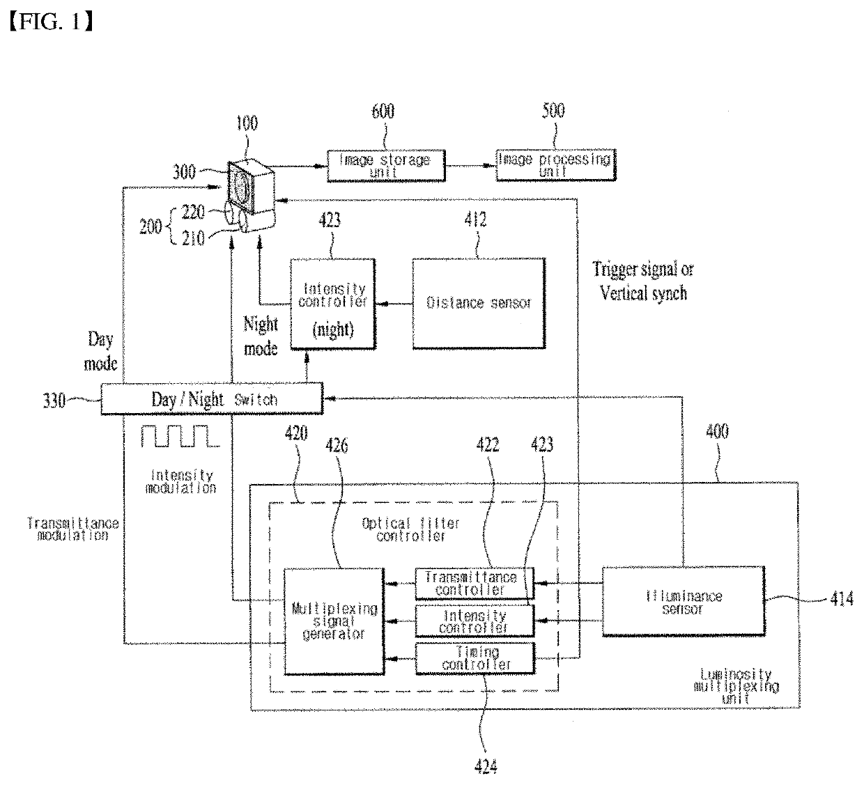
The present patent describes a device and method for acquiring a multi-luminosity image that can be visualized and recognized in different lighting environments. This is achieved by performing a binary luminosity multiplexing method using an optical filter and an infrared lighting. The device can be easily manufactured at low cost using a distance sensor and an illuminance sensor. Additionally, the device can overcome the problem of underexposure or partial overexposure of light by acquiring a composite band multi-image using a modulation in light intensity. Furthermore, the device can respond in real time to changes in external light by proposing a method for modulating the intensity of shooting incident light using a light-adaptive optical filter and an IR lamp. Finally, the device can be easily extended and grafted to mobile camera systems and fixed CCTV cameras.

Problems solved by technology

However, in the existing technology, it is difficult to adjust the camera and the LED lighting adaptively to a distance and a light amount of a subject in case of sever environmental change such as moving shooting, and the hardware configuration corresponding to various functions may be complicated.
Further, it may be difficult to shoot images at a level that human eyes can perceive and adapt to a luminance condition of wide band and a sudden lighting change experienced in daily life by simply increasing the sensitivity of the camera sensor.

Method used


Image

  • Device and method for acquiring multi-luminosity images
  • Device and method for acquiring multi-luminosity images
  • Device and method for acquiring multi-luminosity images

Examples


Embodiment Construction

[0037]Reference will now be made in detail to embodiments of the disclosure, examples of which are illustrated in the accompanying drawings.

[0038]A suffix such as “module” and “unit” for the component used in the following description is merely intended to facilitate description of the present disclosure, and the suffixes “module” and “unit” may be mixed and used.

[0039]Furthermore, embodiments of the present disclosure will be described in detail with reference to the accompanying drawings and the descriptions of the accompanying drawings, but the present disclosure is not limited or restricted by the embodiments.

[0040]Terms used in the present disclosure has been chosen as currently widely used general terms as possible while considering its function in the present disclosure, but may vary depending on the intention or custom of a person skilled in the art or the emergence of new technology. In certain cases, there are also terms arbitrarily selected by the applicant, and in this c...


PUM


Abstract

The present invention relates to a device and a method for acquiring multi-luminosity images, wherein images having multiple luminosities in visible-ray and infrared wavelength domains can be captured and synthesized by using optical filter transmittance adjustment and infrared lighting strength adjustment. The device may comprise: a camera unit for photographing a predetermined subject and acquiring images thereof; a lighting unit disposed on the periphery of the camera unit, the lighting unit comprising a first infrared lamp for modulating and emitting infrared light according to the distance from the subject and a second infrared lamp for modulating and emitting infrared light according to the photography environment; an optical filter unit disposed on the front surface of the camera unit so as to adjust the amount of transmission of light directed to the camera unit; a lamp control unit for controlling the first infrared lamp such that infrared light is modulated on the basis of the distance from the subject; a luminosity multiplexing unit for producing a light multiplexing signal so as to control infrared light modulation by the second infrared lamp and the transmittance of the optical filter unit on the basis of the photography environment; and an image processing unit for synthesizing and processing multiple captured images.

Description

TECHNICAL FIELD[0001]The present disclosure relates to a multi-luminosity image acquiring device, and more particularly to a device and method for acquiring a multi-luminosity image capable of shooting and fusing multi-luminosity images in visible and infrared wavelength regions by using transmittance adjustment of an optical filter and intensity adjustment of an infrared lighting.BACKGROUND ART[0002]To identify outdoor objects in CCTV surveillance cameras, vehicles, robots, drones, etc., camera shooting conditions may generally include daylight conditions from day to night, dark indoors, tunnels, basements, night lights, vehicle headlights, and indoor environments with no light.[0003]Currently, it is a general trend to be converted to HD-class IP cameras according to the consumer demand for high-precision image quality in various environments, and to use LED lights as an auxiliary to increase the sensitivity of a camera sensor or to shoot at night or dark places in a closed space.[...

Claims


Application Information

Patent Timeline
IPC IPC(8): G02B27/10H04N5/225H04N5/235G02B5/20
CPCG02B27/1013H04N5/2258H04N5/2351G02B5/208G03B11/00H04N23/56H04N23/75H04N23/11G02B5/20H04N23/45H04N23/55H04N25/134H04N23/71
Inventor LEE, SUNG HAKJUN, SUN GON
Owner KYUNGPOOK NAT UNIV IND ACADEMIC COOP FOUND
Learn More