
Methods and Systems for Generation of Balanced Secondary Clocks from Root Clock

a technology of secondary clocks and clock edges, applied in the direction of pulse automatic control, pulse generation with predetermined statistical distribution, generating/distributing signals, etc., can solve the problem of digital spurs in the system, under-utilization of clock edges, and the number of parallel hardware dependent on the division factor

Active Publication Date: 2022-08-25
TEXAS INSTR INC
View PDF0 Cites 0 Cited by
  • Summary
  • Abstract
  • Description
  • Claims
  • Application Information

AI Technical Summary

Benefits of technology

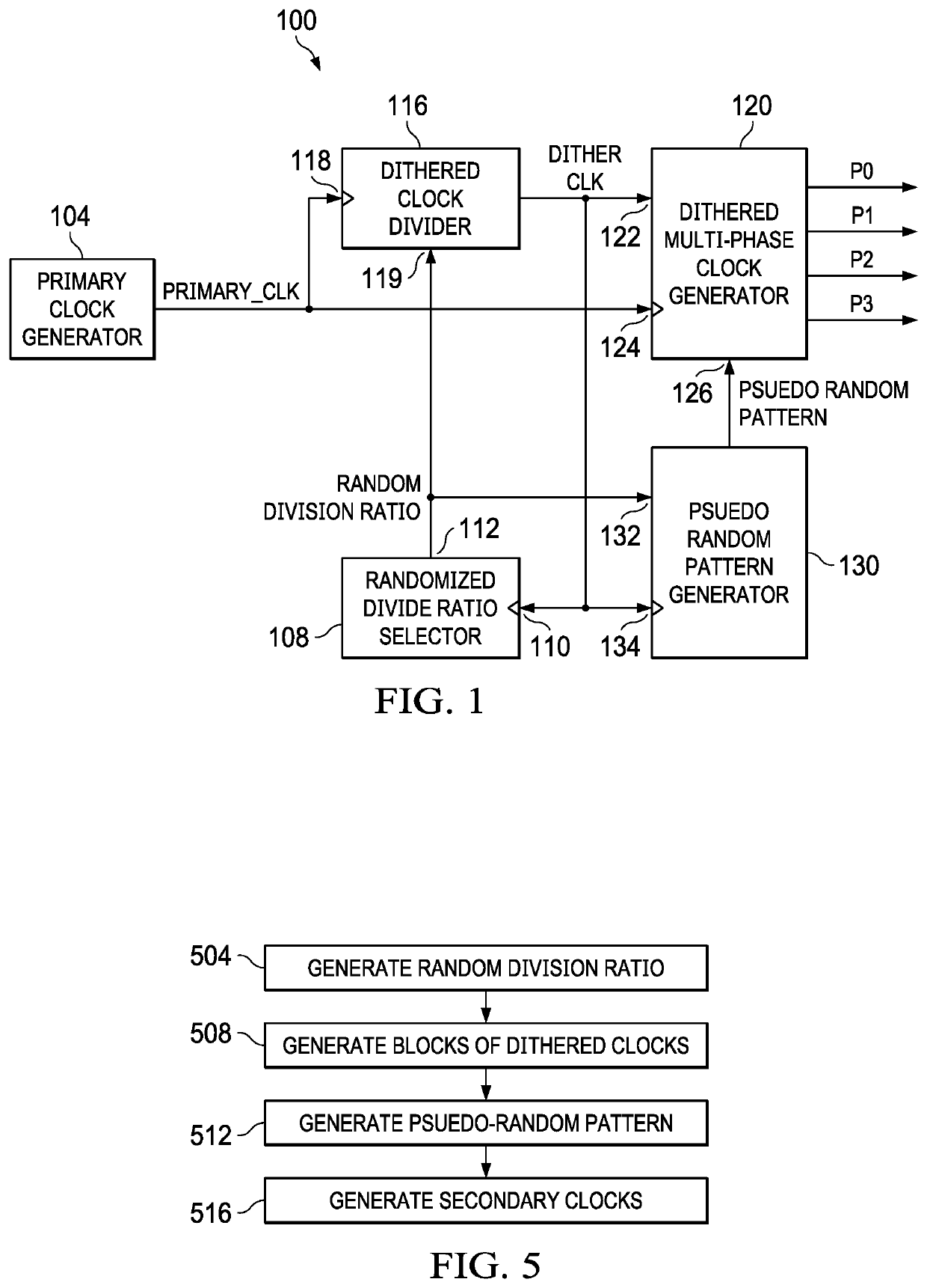
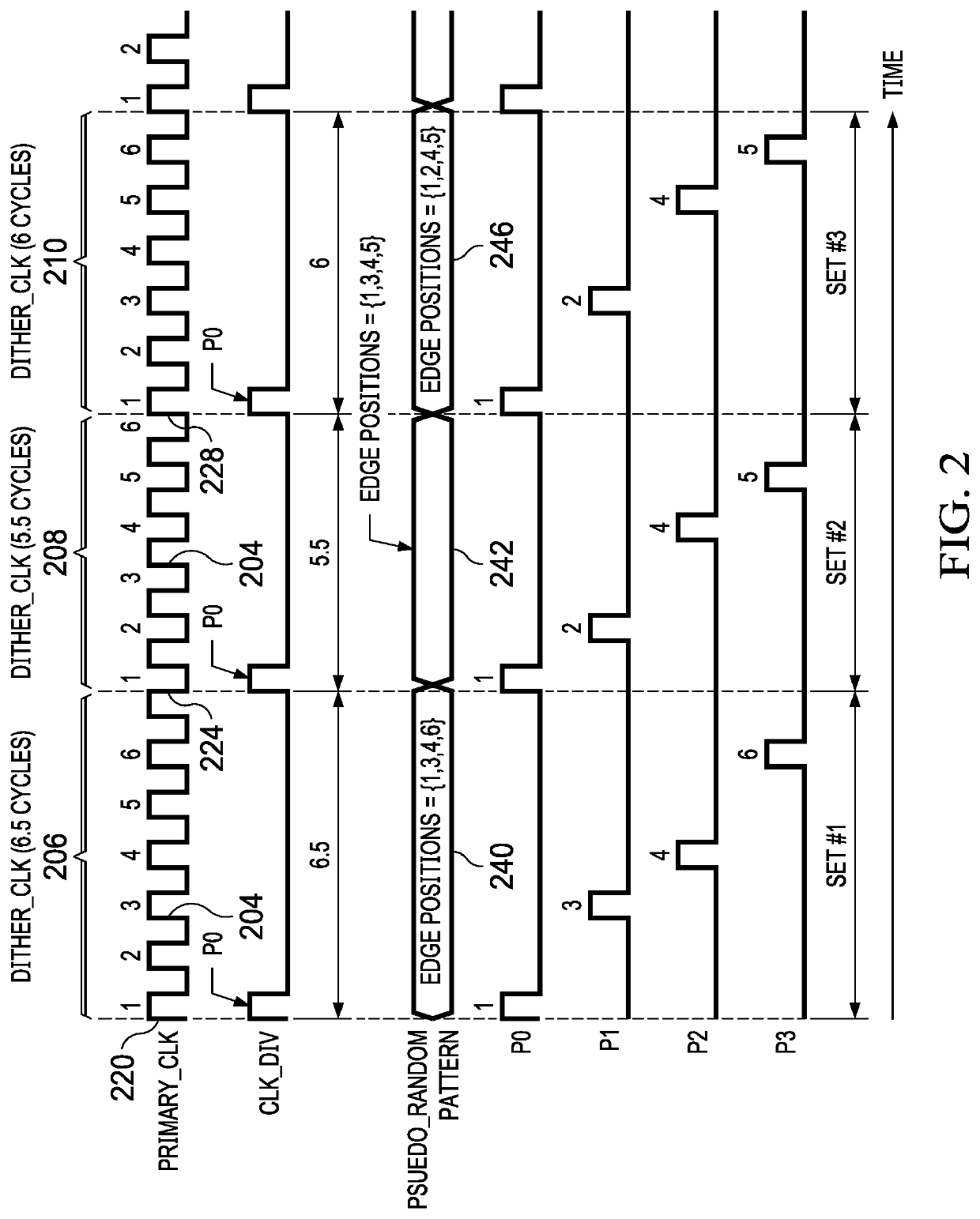
The patent describes a system and method for generating secondary clock signals from a primary clock signal. The system includes a dithered clock divider that divides the primary clock signal into blocks of dithered clock signals based on a random division ratio. The dithered clock signals are then used to generate the secondary clock signals through a multi-phase clock generator. The secondary clock signals include a pseudo-random pattern that indicates their edge positions. A random division ratio selector is used to select the first phase of the dithered clock signal as the primary clock signal for the system. The system can generate multiple secondary clock signals from the dithered clock signal based on the selected phase. This technology allows for the efficient and accurate generation of secondary clock signals for various applications.

Problems solved by technology

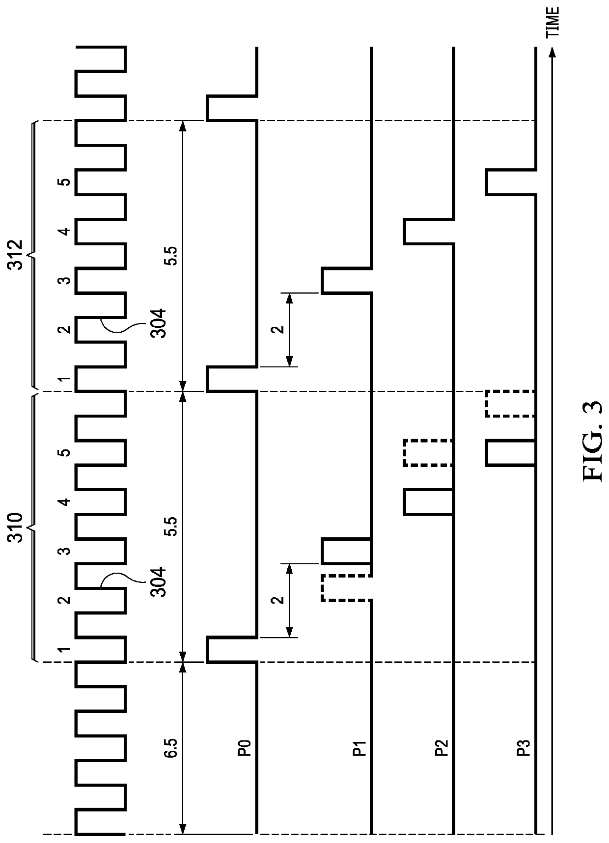
This leads to an under-utilization of clock edges because not all edges of the root clock are utilized, resulting in digital spurs in the system.
Thus, a drawback of some existing systems is that the number of parallel hardware depends on the division factor as well as the root clock frequency.
A drawback of other existing systems is that under utilization of all edges of the root clock leads to digital clock spurs which couple to analog circuitry and degrade system performance.
For example, periodic activities of digital circuitry at clock edges cause instantaneous surge in current demand which causes a change (e.g., a slight decrease or “dip”) in a supply voltage, thereby limiting common mode range of analog circuitry.

Method used


Image

  • Methods and Systems for Generation of Balanced Secondary Clocks from Root Clock
  • Methods and Systems for Generation of Balanced Secondary Clocks from Root Clock
  • Methods and Systems for Generation of Balanced Secondary Clocks from Root Clock

Examples


Embodiment Construction

[0021]FIG. 1 is a block diagram of a system 100 of an example embodiment. The system 100 includes a primary clock generator 104 which provides a primary clock signal PRIMARY_CLK. The system 100 derives four secondary clock signals from the primary clock signal PRIMARY_CLK. The phases P0, P1, P2, and P3, which are the four secondary clock signals, are derived from multiple phases of PRIMARY_CLK. The secondary clock signals are also referred simply as different “phases.” Thus, the first secondary clock signal may be referred to as P0 phase, the second secondary clock may be referred to as P1 phase, the third secondary clock signal may be referred to as P2 phase, and the fourth secondary clock signal may be referred to as P3 phase. The phases P0, P1, P2, and P3 can be provided as clock signals to four parallel hardware (not shown in FIG. 1).

[0022]Although in the example embodiment of FIG. 1, four phases P0, P1, P2, and P3 are derived from the primary clock signal PRIMARY CLK, the syste...


PUM


Abstract

A system for generating secondary clock signals from a primary clock signal includes a dithered clock divider which has a first input adapted to receive the primary clock signal and a second input adapted to receive a random division ratio. The dithered clock divider provides a dithered clock signal. The system includes a multi-phase clock generator which has a first input adapted to receive the primary clock signal, a second input adapted to receive the dithered clock signal, and a third input adapted to receive a pseudo-random pattern. The multi-phase clock generator provides the secondary clock signals from multiple phases of the dithered clock signal. The system includes a pseuodo-random pattern generator which provides the pseudo-random pattern.

Description

CROSS REFERENCE TO RELATED APPLICATIONS[0001]This application claims priority from Indian Provisional Application No. 202141007690, filed Feb. 24, 2021, incorporated herein by reference in its entirety.BACKGROUND[0002]The disclosure generally relates to generation of balanced secondary clocks from a root clock.Description of the Related Art[0003]In RF communication and other mixed signal systems, analog circuitry may operate in the gigahertz (GHz) range while digital circuitry may operate at lower frequencies (e.g., 400-500 MHz) for optimal power efficiency. For example, in a radio base station, a mixer, a phase lock loop, and an up-converter may operate at 3 GHz while a serial data interface and a digital pre-distortion may operate at 500 MHz. Existing systems generally require a number of identical parallel hardware working in unison to derive secondary clocks from a root clock (also called primary clock). In one existing method, the root clock is divided using a clock divider whi...

Claims


Application Information

Patent Timeline
Patent Type & Authority Applications(United States)
IPC IPC(8): H03L7/10H03L7/099H03L7/089H03L7/197G06F7/58
CPCH03L7/104H03L7/0992H03L7/089H03L7/1974G06F7/582G06F1/08G06F1/10H03K3/84
Inventor VS, ASWATHRANGACHARI, SUNDARRAJANGUNTURI, SARMA SUNDARESWARAPENNAM, SANJAY
Owner TEXAS INSTR INC
Learn More