Dynamic compression devices and processes for making and using same

a compression device and dynamic technology, applied in the field of dynamic compression devices and processes for making and using same, can solve the problems of insufficient or discontinuous compression, insufficient healing at the fracture site, and performance issues of compression

Active Publication Date: 2022-08-25
MEDSHAPE
View PDF4 Cites 0 Cited by
  • Summary
  • Abstract
  • Description
  • Claims
  • Application Information

AI Technical Summary

Benefits of technology

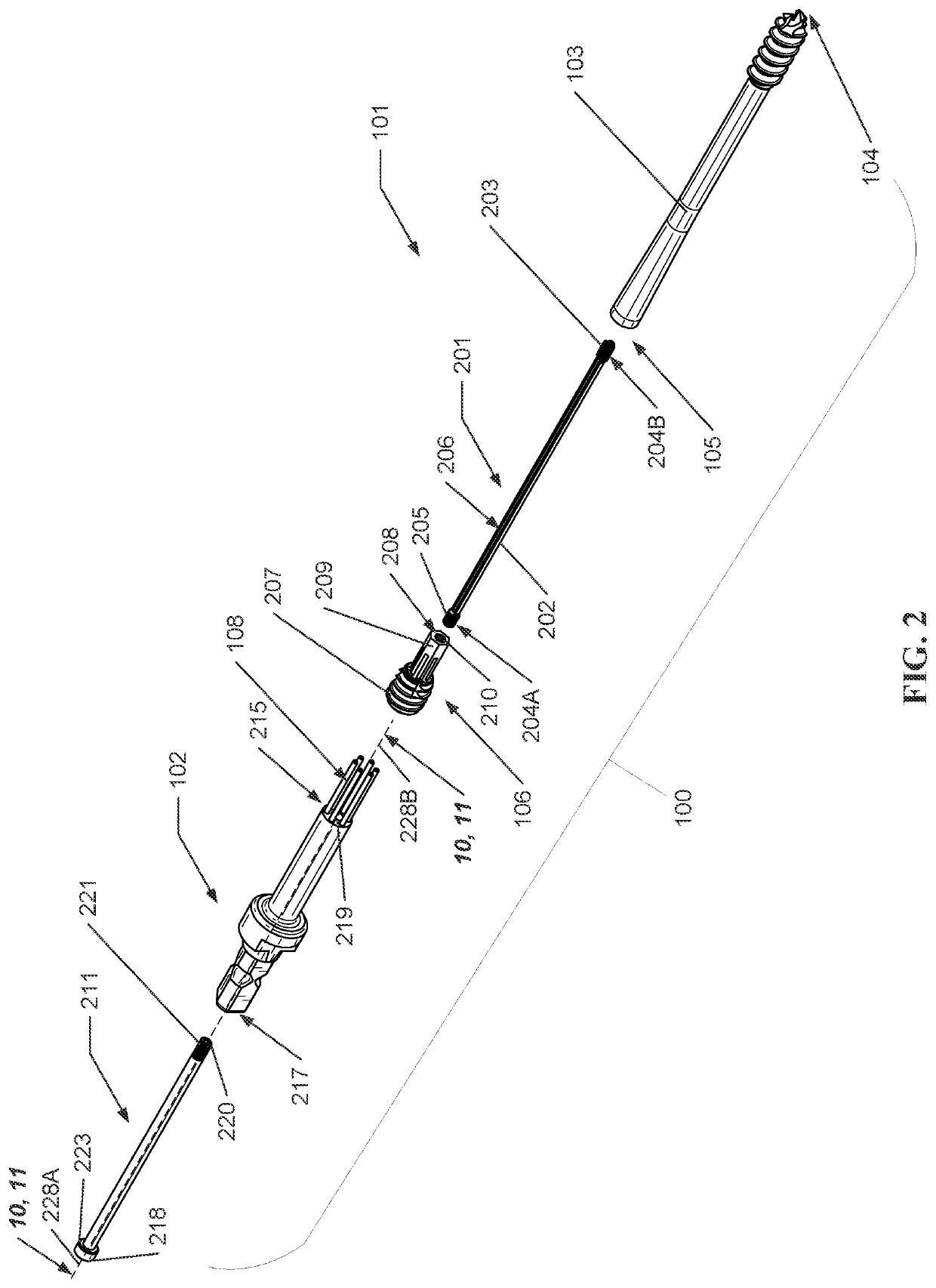
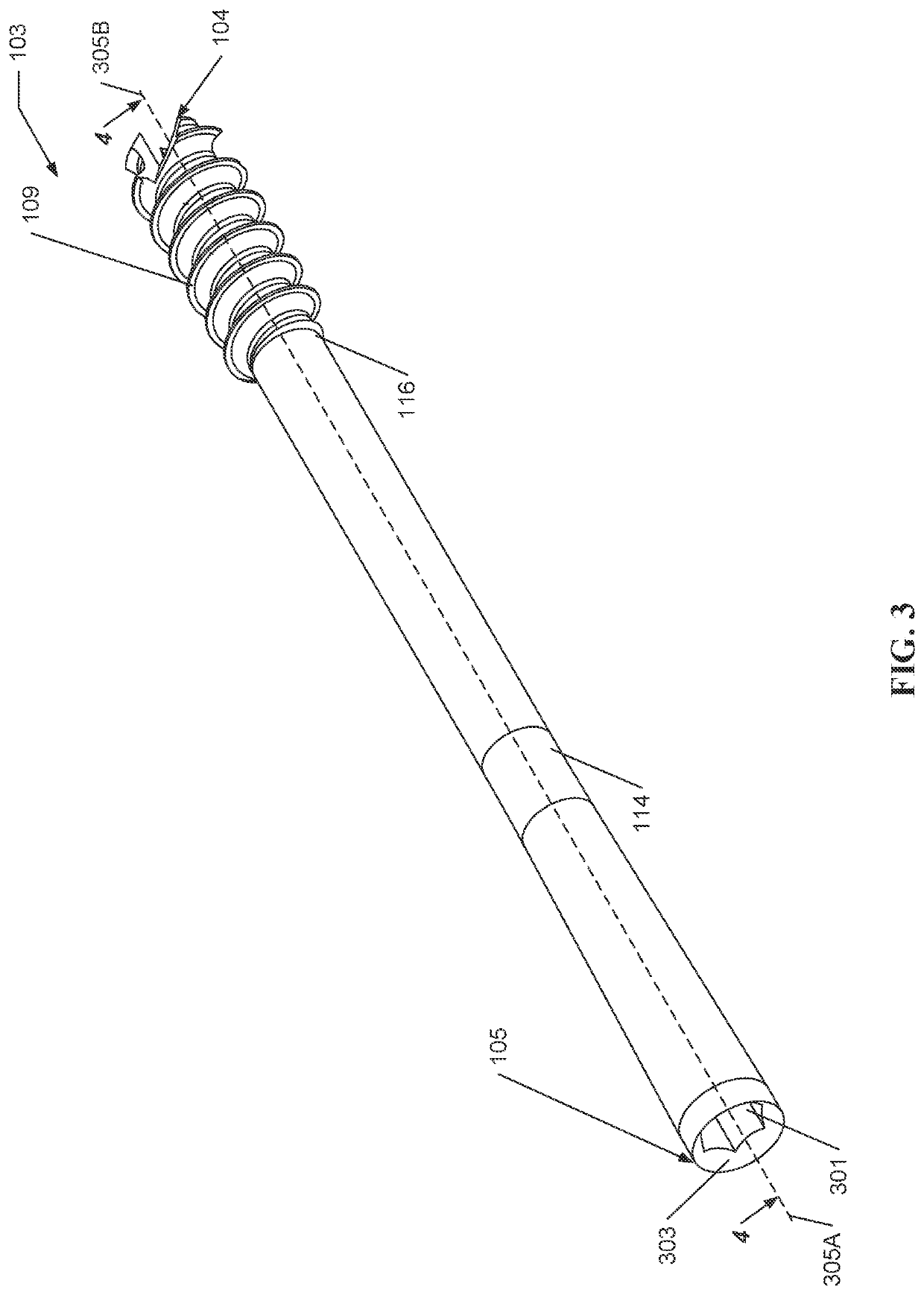
[0005]According to one embodiment, a compression device provides sustained compression to a target site by maintaining a predetermined level of tension between a first device portion affixed to a first bony fragment and a second device portion affixed to a second bony fragment. In various embodiments, the compression device compresses the first bony fragment and second bony fragment to stimulate bone resorption along one or more planes of contact and, thereby, promote healing of the bony fragments. In one or more embodiments, a compression device includes, but is not limited to, a threaded body, a sliding element, and a compression element connecting the threaded body and the sliding element. According to one embodiment, upon implantation, the threaded body is affixed to a first bony fragment and the sliding element is affixed to a second bony fragment. In at least one embodiment, upon being engaged, the compression element applies sustained tension to the sliding element and opposing tension to the threaded body, thereby compressing the first bony fragment and the second bony fragment along a plane of contact. In one or more embodiments, in contrast to previous solutions, the continuous tension of the sliding element generates substantially sustained compression at the plane of contact, which may be sustained even with resorption and / or resettling of the first and second bony fragments.
[0016]In various embodiments, the compression device includes one or more mechanisms for precisely and accurately stretching the compression element, thereby providing a controlled pre-tensioning of the compression element and, thus, an accurate configuration of a desired compression performance. In one or more embodiments, the one or more mechanisms include a connection bolt and an insertion tool. In one or more embodiments, the insertion tool includes a plurality of pins that are inserted through voids in the sliding element such that the plurality of pins contact an end of the threaded body (e.g., the sliding element and threaded body being connected at either end of the compression element). According to one embodiment, the insertion tool is cannulated such that the connection bolt may be received through and freely rotate within the insertion tool. In at least one embodiment, a length of the connection bolt is greater than a length of the insertion tool such that, upon insertion, the connection bolt extends through a first end of the insertion tool and a second end of the insertion tool. In one or more embodiments, the connection bolt and sliding element include corresponding threads such that a secure, threaded connection is formed as the connection bolt is inserted through the insertion tool and rotated into the sliding element.

Problems solved by technology

However, these previous approaches typically suffer compression performance issues, such as insufficient or discontinuous compression.
In this example, the inability of the threaded compression device to adapt to changes at the insertion site and provide a dynamic compressive force may result in insufficient healing at the fracture site (e.g., potentially requiring revision surgery, additional physical therapy, assistive devices, etc.).
Therefore, there is a long-felt but unresolved need for a dynamic compression device that allows for dynamic generation of sustained compressive forces between bony fragments.

Method used


Image

  • Dynamic compression devices and processes for making and using same
  • Dynamic compression devices and processes for making and using same
  • Dynamic compression devices and processes for making and using same

Examples


Embodiment Construction

[0067]For the purpose of promoting an understanding of the principles of the present disclosure, reference will now be made to the embodiments illustrated in the drawings and specific language will be used to describe the same. It will, nevertheless, be understood that no limitation of the scope of the disclosure is thereby intended; any alterations and further modifications of the described or illustrated embodiments, and any further applications of the principles of the disclosure as illustrated therein are contemplated as would normally occur to one skilled in the art to which the disclosure relates. All limitations of scope should be determined in accordance with and as expressed in the claims.

[0068]Whether a term is capitalized is not considered definitive or limiting of the meaning of a term. As used in this document, a capitalized term shall have the same meaning as an uncapitalized term, unless the context of the usage specifically indicates that a more restrictive meaning f...


PUM


Abstract

A compression device may include, but is not limited to, a threaded body, a sliding element, and a compression element connecting the threaded body and the sliding element. According to one embodiment, upon implantation, the threaded body contacts a first bony fragment and the sliding element contacts to a second bony fragment. In at least one embodiment, upon being engaged, the compression element applies sustained tension to the sliding element and opposing tension to the threaded body, thereby compressing the first bony fragment and the second bony fragment along a plane of contact promoting healing.

Description

CROSS REFERENCE TO RELATED APPLICATIONS[0001]This application is a divisional of U.S. application Ser. No. 17 / 184,104, filed Feb. 24, 2021, entitled “DYNAMIC COMPRESSION DEVICES AND PROCESSES FOR MAKING AND USING SAME,” the disclosure of which is incorporated herein by reference in its entirety.BACKGROUND[0002]Injuries such as fractures may be treated, in part, using continuous compression at the fracture. Compression typically involves compressing two or more bony fragments together to promote ossification and / or resettlement processes and heal the two or more bony fragments. Previous approaches include a threaded compression device that is inserted into and compresses together two or more bony fragments. In such approaches, compressive forces are typically generated by threaded elements extending along at least a portion of the compression device (e.g., for example, at either end of the device). However, these previous approaches typically suffer compression performance issues, su...

Claims


Application Information

Patent Timeline
Patent Type & Authority Applications(United States)
IPC IPC(8): A61B17/86
CPCA61B17/864A61B17/863A61B2017/681A61B17/8685A61B17/8875A61B17/8877A61B2017/8655A61B17/7225A61B17/8625A61B2017/564
Inventor O'FLAHERTY, RYAN WALTERBLAIR, JEREMY WEBSTERGRIFFIN, II, DONALD KENNETH
Owner MEDSHAPE
Why Eureka
Try Eureka