Light transmittance control panel for smart windows and smart window for vehicle with the same

a technology of transmission control and smart windows, which is applied in the direction of instruments, vehicle components, optics, etc., can solve the problems of difficult to secure the driver's field of view, and conventional methods do not have an active control function for sunlight. , to achieve the effect of improving the viewing angle characteristics, high shading rate, and medium-level gray driving characteristics

Inactive Publication Date: 2022-08-11
IMAGELAB +1
View PDF0 Cites 0 Cited by
  • Summary
  • Abstract
  • Description
  • Claims
  • Application Information

AI Technical Summary

Benefits of technology

[0014]In particular, the present invention can omit the polarizing plate, liquid crystal alignment (alignment film), spacer insertion, and sealing processes required for the conventional liquid crystal-based light transmittance control device, thereby dramatically simplifying the manufacturing process and greatly enhancing the light-shielding performance. Even so, it provides a light transmission control panel for a smart window capable of realizing a performance that meets the required optical characteristics of a smart window for a vehicle, and a smart window for a vehicle having the same.
[0022]According to the light transmission control panel according to the present invention, it is possible to implement a very high shading rate and also satisfy the light characteristics essential for a smart window for a vehicle.
[0023]According to the light transmittance control panel following this invention, it has the effect of implementing improved viewing angle characteristics and medium level gray driving characteristics compared to conventional light transmittance control panel.
[0024]According to the light transmission control panel according to the present invention, the polarizing plate, liquid crystal alignment (alignment film), spacer insertion and sealing processes, etc., which were required for the conventional liquid crystal-based light transmittance control device, can be omitted, thereby dramatically simplifying the manufacturing process, and it is possible to significantly reduce manufacturing costs.

Problems solved by technology

However, these conventional methods do not have an active control function for sunlight, and are passive methods of selectively shielding or transmitting only in a certain light wavelength range.
However, Korean Patent Laid-Open Publication No. 10-1998-038075 has a light transmittance of 10% or less due to the use of two polarizing plates, and thus, it is difficult to secure a driver's field of view, so that it is difficult to apply to a smart window for a vehicle.
However, such a conventional light transmittance control device basically uses a polarizing plate, requires alignment of liquid crystals, and requires spacer insertion and liquid crystal layer sealing to control the upper and lower plates.
There is a problem in that it leads to a decrease in haze characteristics, and also increases the manufacturing cost as the number of processes increases.
However, in the case of the conventional PDLC-type transmittance control film, the light passing through the PDLC is converted into scattered light, making the driver's visibility unnatural, which can hinder the driver's safe driving, so it is actually applied to a smart window for a vehicle.
There was a difficult limit.

Method used


Image

  • Light transmittance control panel for smart windows and smart window for vehicle with the same
  • Light transmittance control panel for smart windows and smart window for vehicle with the same
  • Light transmittance control panel for smart windows and smart window for vehicle with the same

Examples


Embodiment Construction

[0036]The present invention particularly relates to a light transmission control panel for a smart window that is attached to a window of a vehicle and is capable of selectively driving a light-blocking mode for blocking light incident to the window and a transmission mode for transmitting the incident light.

[0037]In particular, the present invention relates to a light transmission control panel for a smart window capable of significantly increasing a light blocking rate in a light-blocking mode and sufficiently securing light transmittance and visibility in a front / side / rear / upper direction of a vehicle in a transmission mode.

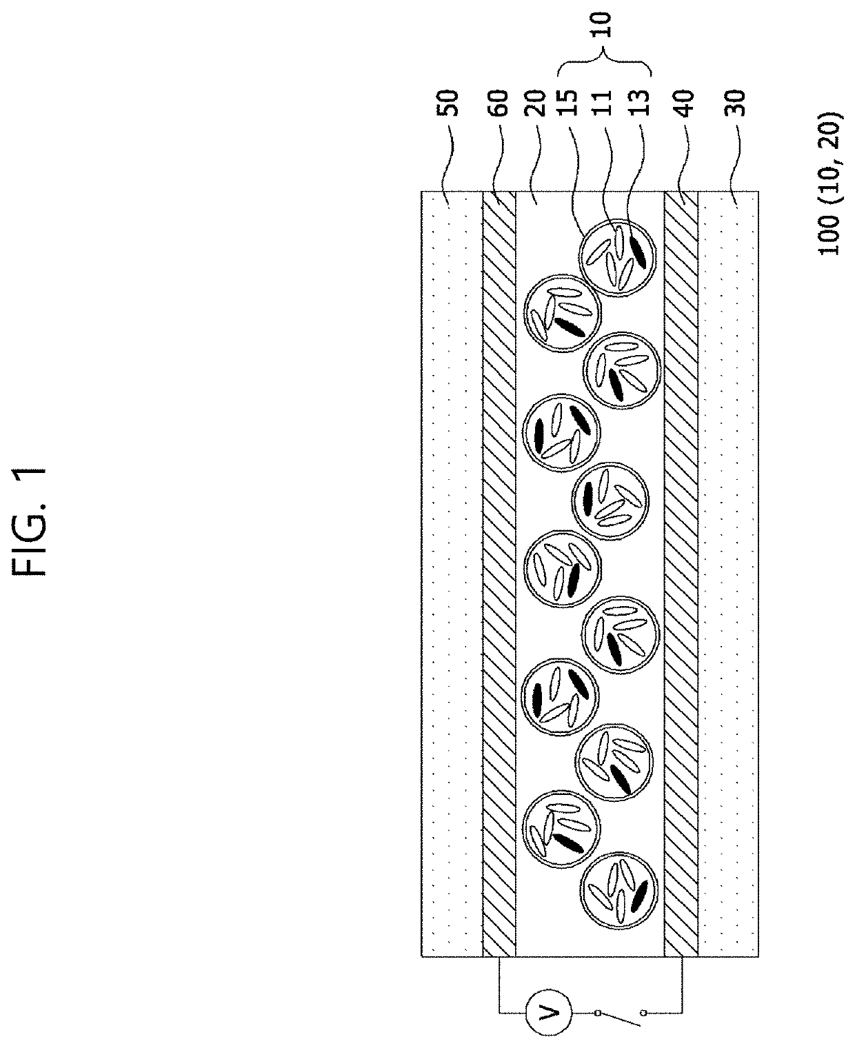
[0038]FIG. 1 is a cross-sectional view of a light transmission control panel for a smart window according to the present invention. Referring to FIG. 1, a light transmission control panel for a smart window according to the present invention includes a first substrate 30, a first electrode 40, a second substrate 50, a second electrode 60, and a liquid crystal ...


PUM

PropertyMeasurementUnit
particle sizeaaaaaaaaaa
light transmittanceaaaaaaaaaa
thicknessaaaaaaaaaa

Abstract

The present invention relates to a light transmission control panel for a smart window capable of actively adjusting light transmittance as necessary, and a smart window for a vehicle having the same. The present invention discloses The light transmission control panel for a smart window comprising: a first substrate on which a first electrode formed on one surface; a second substrate on which a second electrode is formed on one surface; and a liquid crystal capsule layer provided between the first substrate and the second substrate. According to the present invention of the light transmittance control panel, it has the effect of implementing improved viewing angle characteristics and medium level gray driving characteristics compared to conventional light transmittance control panel.

Description

CROSS-REFERENCE TO RELATED APPLICATIONS[0001]This application is a continuation of U.S. application Ser. No. 17 / 099,505, filed Nov. 16, 2020 in the U.S. Patent and Trademark Office. All disclosures of the document named above are incorporated herein by reference.BACKGROUND OF THE INVENTIONField of the Invention[0002]The present invention relates to a light transmission control device, and more particularly, to a light transmission control panel for a smart window capable of implementing a light-blocking mode and a transmission mode.Description of the Related Art[0003]A smart window refers to a window in which the transmittance of sunlight can be freely adjusted, and is also called an electronic curtain, variable transmittance glass, and dimming glass.[0004]Conventionally, in order to control the transmittance of sunlight flowing into the room through the glass, a method of making a colored glass by adding a colored oxide to a glass composition, or attaching a film paper having a spe...

Claims


Application Information

Patent Timeline
Patent Type & Authority Applications(United States)
IPC IPC(8): B60J3/04G02F1/1343G02F1/1334G02F1/137
CPCB60J3/04G02F1/134309G02F1/1334G02F1/13706G02F2202/043G02F2202/28G02F1/137
Inventor HWANG, HYUNHA
Owner IMAGELAB
Why Eureka
Try Eureka