
Method and device for energy harvesting and charging rechargeable energy storage devices

Pending Publication Date: 2022-07-28
E PEAS SA
View PDF0 Cites 0 Cited by
  • Summary
  • Abstract
  • Description
  • Claims
  • Application Information

AI Technical Summary

Benefits of technology

This patent describes a method and device for efficient energy harvesting and charging of a rechargeable storage device. The technical effects include faster starting of the application load and continued operation even under conditions where the energy harvester is interrupted. Additionally, the patent describes a second rechargeable storage device that can be used as an alternative energy source to the first rechargeable storage device when the energy harvester is not operating. This allows for continuous operation of the application load without interruption. The patent also provides a second power input path for transferring input power from a third terminal to the voltage converter system, which allows for charging of both the first and second rechargeable storage devices simultaneously.

Problems solved by technology

One of the problems with the known energy harvesting systems is that when initially starting with a depleted rechargeable storage device, it takes a long time to initially charge the rechargeable storage device with energy from the energy harvester.
As a consequence, it also takes a long time before the application load can receive power from the rechargeable storage device and start operating.
Especially if the rechargeable storage device is a supercapacitor, being at zero Volt when fully de-charged, the charging time of the supercapacitor can be very long.
But also charging rechargeable batteries to a required charging level for being ready supplying power to an application load during a sufficiently long time period can take a considerable long charging time.
A second problem is related to the variable conditions inherent to energy harvesting systems which result in situations where the energy harvester is not supplying continuously energy over a longer period of time, e.g. over time periods of multiple days.
Depending on the type of energy harvester, energy harvesting can be interrupted over considerable long time intervals, e.g. time intervals of several hours, which degrades the reliability and long term functionality of the application load.
Depending on the power consumption of the application load, this can result in an application load being stopped from operating.

Method used


Image

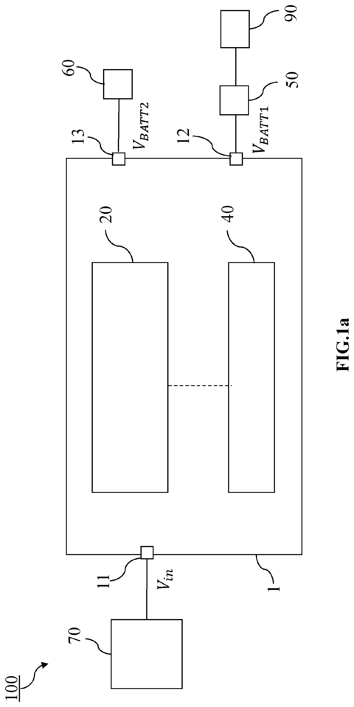
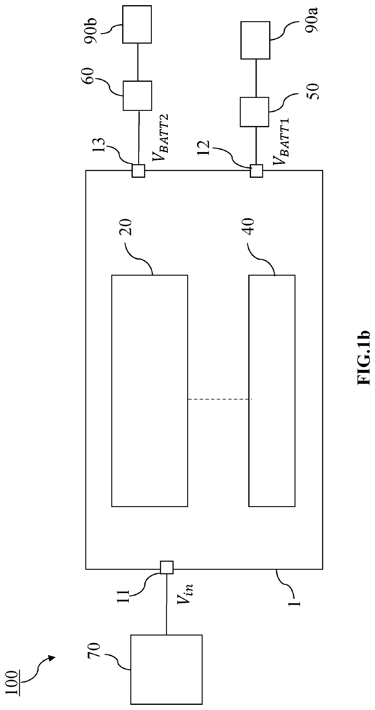
  • Method and device for energy harvesting and charging rechargeable energy storage devices
  • Method and device for energy harvesting and charging rechargeable energy storage devices
  • Method and device for energy harvesting and charging rechargeable energy storage devices

Examples


Embodiment Construction

[0042]The present disclosure will be described in terms of specific embodiments, which are illustrative of the disclosure and not to be construed as limiting. It will be appreciated by persons skilled in the art that the present disclosure is not limited by what has been particularly shown and / or described and that alternatives or modified embodiments could be developed in the light of the overall teaching of this disclosure. The drawings described are only schematic and are non-limiting.

[0043]Use of the verb “to comprise”, as well as the respective conjugations, does not exclude the presence of elements other than those stated.

[0044]Furthermore, the terms first, second and the like in the description and in the claims, are used for distinguishing between similar elements and not necessarily for describing a sequence, either temporally, spatially, in ranking or in any other manner. It is to be understood that the terms so used are interchangeable under appropriate circumstances and ...


PUM


Abstract

A method for energy harvesting and charging energy storage devices is provided. The method uses a voltage converter system and includes the steps of monitoring a parameter VBatt1 indicative of a charging level of a first rechargeable storage device and of maintaining this parameter VBatt1 between a lower and an upper threshold value. The method further includes steps of charging a second rechargeable storage device and operating the voltage converter system for transferring charges from the second to the first rechargeable storage device. An integrated circuit for energy harvesting is provided in which a terminal connectable with a second rechargeable storage device is switchably coupled to both the input and the output of the voltage converter system.

Description

FIELD OF THE INVENTION[0001]The invention relates to a method and device for energy harvesting. More specifically, it relates to a method and device for charging rechargeable energy storage devices.DESCRIPTION OF PRIOR ART[0002]The use of voltage converters for extracting energy from an energy harvester and charging an energy storage device are well known in the art. For example in WO2018234485, an integrated circuit comprising a voltage converter is described for transferring energy from an energy harvester to a rechargeable storage device. The energy stored in the rechargeable storage device is then used as a power source for an application load. The application load can be coupled directly or indirectly to the storage device. An indirect coupling is for example established by placing an auxiliary voltage converter between the storage device and the application load and wherein the auxiliary voltage converter is configured for regulating a specific required voltage for the applica...

Claims


Application Information

Patent Timeline
IPC IPC(8): H02J50/00H02J7/00H02J7/34H02M3/158
CPCH02J50/001H02J7/0048H02J7/0013H02J7/0063H02J7/345H02J7/342H02M3/1582H02J2207/20H02J7/007182H02J7/34H02J50/00H02J50/20
Inventor DE VOS, JULIENGOSSET, GEOFFROY
Owner E PEAS SA
Learn More