Lighting device with light-emitting filaments

a technology of light-emitting filaments and light-emitting devices, which is applied in the direction of semiconductor devices for light sources, light and heating apparatus, fixed installations, etc., can solve the problems of -emitting filaments, manufacturing difficulties, and difficulty in achieving a sufficient level of luminous power

Active Publication Date: 2022-07-28
SIGNIFY HLDG BV
View PDF4 Cites 0 Cited by
  • Summary
  • Abstract
  • Description
  • Claims
  • Application Information

AI Technical Summary

Benefits of technology

The present invention is a lighting device that uses solid-state lighting technology to generate sufficient luminosity for various applications. It is cost-effective and technically simple to manufacture. The lighting device can emit homogeneously distributed light from what appears to be a surface, making it ideal for linear lighting applications. By arranging multiple light-emitting filaments close together, the brightness of the lighting device is increased. The amount of overlap between the light-emitting filaments depends on factors such as their distance from the circuit board and the ratio between their length and the distance between the tracks. The lighting device may also include a reflective surface and side reflectors to direct the light emitted by the light-emitting filaments.

Problems solved by technology

Some of the challenges encountered when developing new applications include difficulties in achieving a sufficient level of luminous power as well as manufacturing difficulties due to, for example, the light-emitting filaments being relatively fragile.

Method used


Image

  • Lighting device with light-emitting filaments
  • Lighting device with light-emitting filaments
  • Lighting device with light-emitting filaments

Examples


Embodiment Construction

[0035]The present invention will now be described more fully hereinafter with reference to the accompanying drawings, in which currently preferred embodiments of the invention are shown. This invention may, however, be embodied in many different forms and should not be construed as limited to the embodiments set forth herein; rather, these embodiments are provided for thoroughness and completeness, and fully convey the scope of the invention to the skilled person.

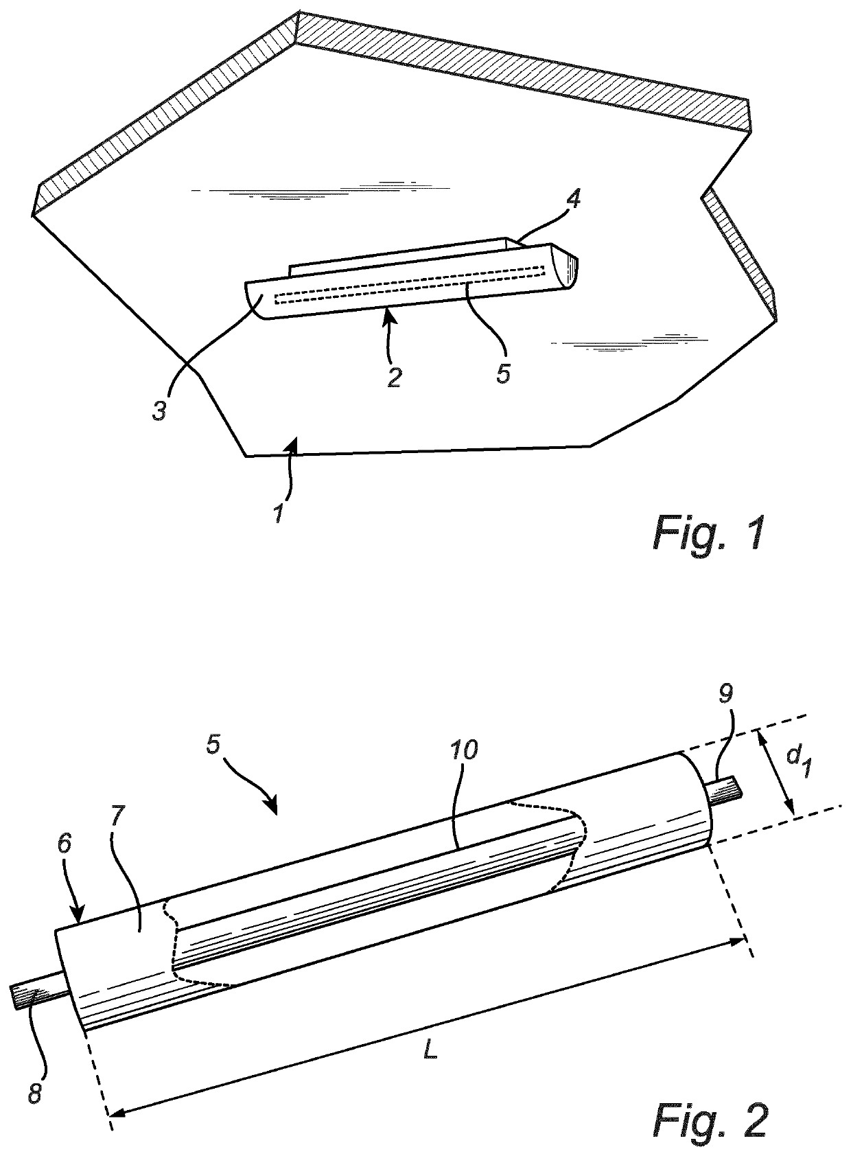
[0036]FIG. 1 shows an example of a luminaire 1. The luminaire 1 illustrated in FIG. 1 is a ceiling-mounted lamp, more specifically an LED batten. The luminaire 1 may be of a different type in a different example and may be intended for outdoor illumination instead of indoor illumination. The luminaire 1 here comprises a cover 2, which includes a light exit window 3, and a connection 4 which is electrically connected to the mains electricity supply. In this case, the connection 4 also allows the luminaire 1 to be mechanicall...


PUM


Abstract

There is presented a lighting device comprising: several light-emitting filaments (15, 15′) with solid-state light sources and a circuit board (10) with first and second electrically conductive tracks (13, 14) following first and second paths, respectively. Each light-emitting filament (15, 15′) comprises a first electrical contact (19, 19′) electrically connected to the first track (13) at a first point on the first path, and a second electrical contact (20, 20′) electrically connected to the second track (14) at a second point on the second path. The first and second points associated with each light-emitting filament (15, 15′) are arranged on an axis (A) which is non-perpendicular to a tangent (T1) to the first path at the first point and to a tangent (T2) to the second path at the second point. The lighting device may be adapted to emit light from what appears to be a surface according to an observer.

Description

FIELD OF THE INVENTION[0001]The present invention relates to a lighting device with light-emitting filaments based on solid-state lighting technology.BACKGROUND OF THE INVENTION[0002]Light-emitting filaments based on solid-state lighting technology have traditionally been used in light bulbs designed to resemble traditional incandescent light bulbs. An example of such a light bulb is disclosed in CN104075169A, which includes a pear-shaped bulb inside which several parallel light-emitting diode (LED) filaments extend between two circular wires which are connected to the ends of the LED filaments.[0003]There is currently much interest in using light-emitting filaments based on solid-state lighting technology in other lighting applications than light bulbs such as the one disclosed in CN104075169A. Some of the challenges encountered when developing new applications include difficulties in achieving a sufficient level of luminous power as well as manufacturing difficulties due to, for e...

Claims


Application Information

Patent Timeline
IPC IPC(8): F21V23/00F21V19/00F21V23/06
CPCF21V23/006F21Y2103/10F21V23/06F21V19/0035F21S8/04F21V19/005F21Y2115/10F21V7/05
Inventor VAN BOMMEL, TIESHIKMET, RIFAT ATA MUSTAFAPET, ROBERT JACOB
Owner SIGNIFY HLDG BV
Why Eureka
Try Eureka