
Method for Producing a Lost Casting Core

a casting core and casting core technology, applied in the direction of foundry patterns, metal-working equipment, foundry moulding apparatus, etc., can solve the problems of dividing the core, crack formation, and often not being able to dimension

Pending Publication Date: 2022-07-28
NEMAK S A B DE
View PDF0 Cites 0 Cited by
  • Summary
  • Abstract
  • Description
  • Claims
  • Application Information

AI Technical Summary

Benefits of technology

The invention relates to a method for producing a casting core insert for casting purposes. This method involves first pre-fabricating the casting core insert from molding material, which is then destroyed during unmolding of the cast part. This pre-fabrication process allows for easy shaping of the casting core insert without any unwanted deviations from its intended shape. Surprisingly, no burr is present in the transition region, which is formed by the molding material introduced into the mold cavity after positioning of the casting core insert. The method can be implemented easily in existing core-shooting machines without changing their design. It also provides a particularly efficient version that allows for a continuous mass production by repeatedly carrying out the work steps in a serial sequence and providing an additional mold cavity for pre-fabricating the new casting core insert in each pass.

Problems solved by technology

The core dividing burr arises from molding material that unavoidably penetrates into the separating joins between the box parts when the molding material is shot into the mold cavity of the core box.
In practical use of the cast part, stress peaks can occur at such a notch-like depression, and these can lead to crack formation, going as far as failure of the cast part.
For this reason, it has been necessary until now to design cast parts, in those regions in which the core dividing burr of the corresponding casting core leaves an undesirable but unavoidable depression, caused by production technology, during production, in such a manner that they can reliably withstand the stresses that occur in practice, in spite of the depression in question.
However, in the case of particularly delicately shaped cast parts that are subject to great stress in practice, such as cylinder heads for high-compression internal combustion engines or the like, which are cast from light-metal material and in which only minimal wall thicknesses of the cast part are permitted due to their design and function, such dimensioning is frequently not possible.
However, not only are there narrow limits set for this measure, not only as a consequence of the restricted accessibility of the mold cavity, but rather it also proves to be unreliable for the process in large-scale mass production, since it cannot be guaranteed with sufficient reliability that on the one hand, the separating joins will in fact be closed with a sufficient seal, and, on the other hand, no filling compound will get into the mold cavity, and the precision with which the molding casting core is reproduced is impaired.
Likewise, it proves to be impossible or only possible with extreme effort to lay out the parting planes and thereby the separating joins of a core box in such a manner that the casting core burr runs at a location at which it does not lead to any impairment of the usage properties on the cast part to be formed using the casting core in question, or can be easily taken into consideration in the design of the cast part.

Method used


Image

  • Method for Producing a Lost Casting Core
  • Method for Producing a Lost Casting Core
  • Method for Producing a Lost Casting Core

Examples


Embodiment Construction

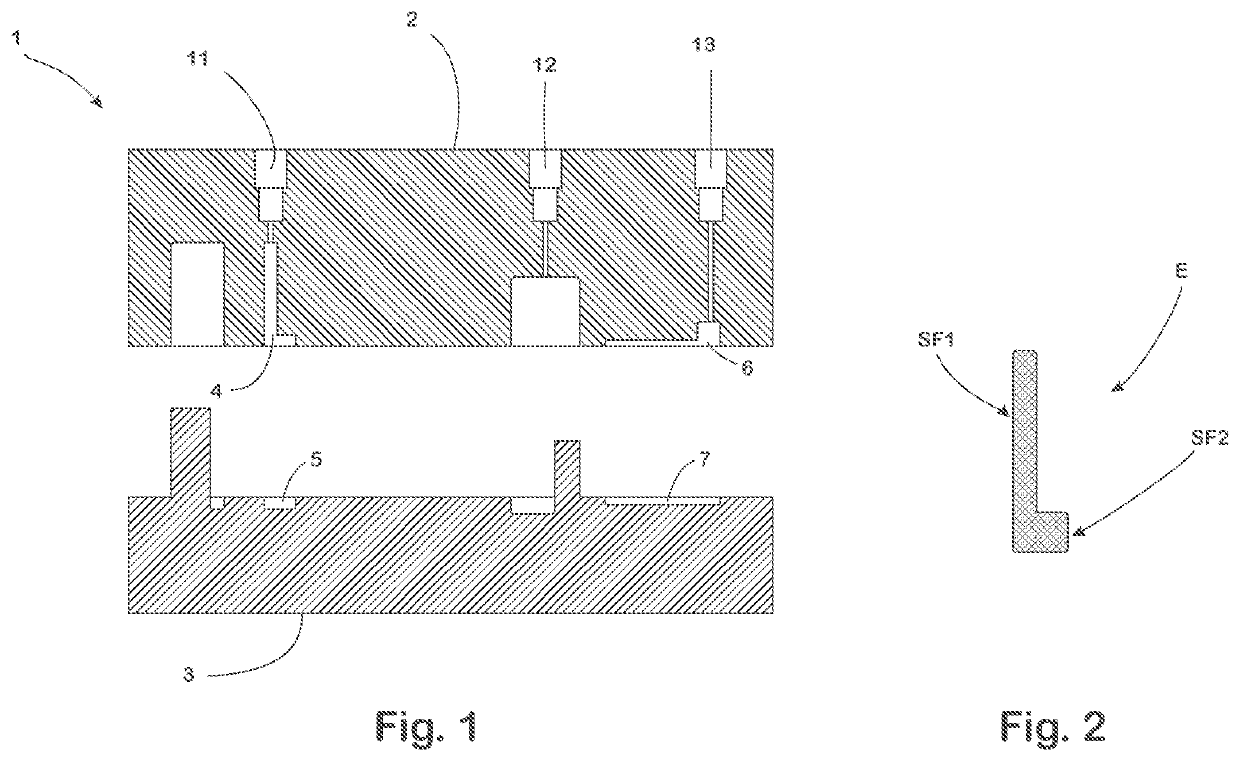
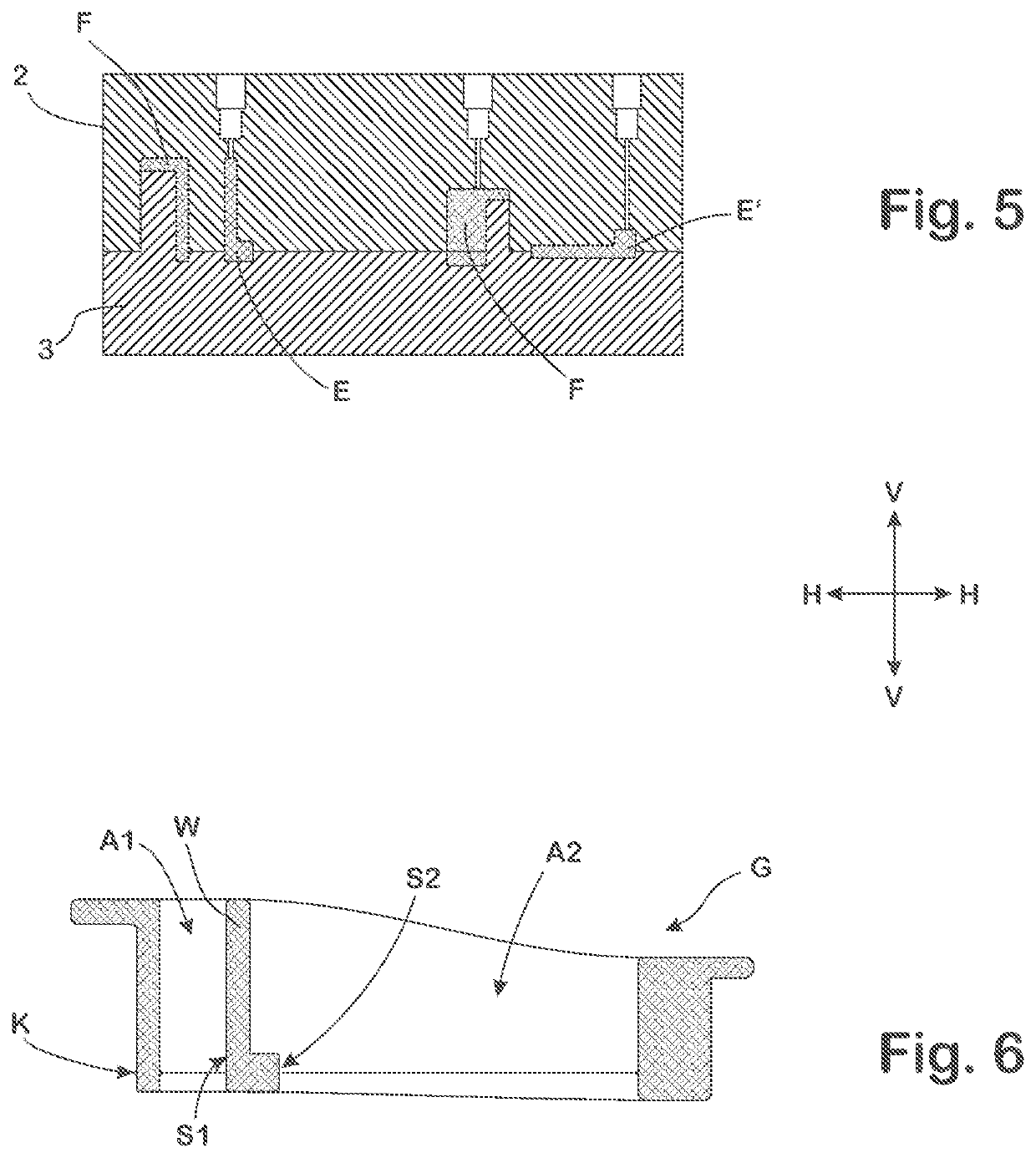
[0043]For the production of a casting core G shown schematically in FIG. 6, in a sectional representation, and in greater detail in FIG. 8, a core box 1 is made available in a conventional core-shooter, not shown in any detail here, which box comprises an upper core box part 2 and a lower core box part 3.

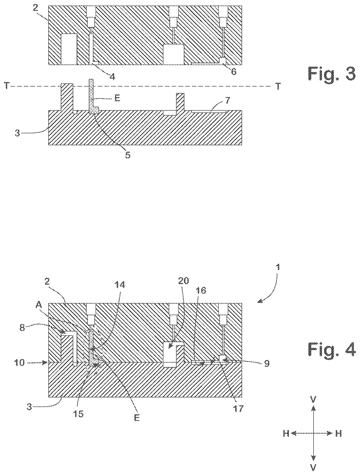
[0044]In the upper and lower core boxes 1, recesses 4, 5, 6, 7 are formed, in each instance, of which the recess 4 of the upper core box part 2 and the recess 5 of the lower core box part 3 jointly form a mold cavity 8 when the core box 1 is closed (FIG. 4, 5), the shape of which cavity corresponds to a negative of the casting core G to be produced. The recess 6 of the upper core box part 2 and the recess 7 of the lower core box part 3, in contrast, form an additional mold cavity 9 when the core box 1 is closed, which cavity is independent of the first mold cavity 8 and represents a negative of a casting core insert E.

[0045]A separating join 10 runs between the core box parts 2, 3, ...


PUM


Abstract

The invention names a method for producing a lost casting core (G), which has a side surface (S1, S2), in a core box (1) that is divided into two core box parts (2, 3) in a parting plane (T), and which box delimits a mold cavity (8) in which an inner surface (14, 15) that reproduces the side surface (S1, S2) of the casting core (G) is provided, through which surface the parting plane (T) of the core box (1) runs. To prevent a burr in a critical section of the side surfaces (S1, S2) of the casting core (G), the following work steps are carried out:(a) producing a casting core insert (E) having a side surface section (SF1, SF2) that is equal to a corresponding section of the side surface of the casting core (G), from a casting core molding material (F);(b) positioning the casting core insert (E) in the mold cavity (8) of the core box (1) in such a manner that the side surface section (SF1, SF2) of the casting core insert (E) sits in the place of the corresponding section of the side surface (S1, S2) of the finished casting core (G), wherein the parting plane (T) runs through the side surface section (SF1, SF2);(c) introducing a casting core molding material (F) into the mold cavity (8) of the core box (1), so as to form the remaining casting core (G), wherein the introduced casting core molding material (F) comes into contact with the casting core insert (E);(d) solidifying the casting core molding material (F), thereby forming a shape-fit and / or material-fit connection between the introduced casting core molding material (F) and the casting core insert (E).

Description

CROSS-REFERENCE TO RELATED APPLICATIONS[0001]This application is the United States national phase of International Application No. PCT / IB2020 / 054721 filed May 19, 2020, and claims priority to German Patent Application No. 10 2019 114 493.0 filed May 29, 2019, the disclosures of which are hereby incorporated by reference in their entirety.BACKGROUND OF THE INVENTION1. Field of the Invention[0002]The invention relates to a method for producing a lost casting core, which has a side surface, in a core box, which is composed of at least two core box parts, between which parts a parting plane runs when the core box is closed, and which box delimits a mold cavity that determines the shape of the casting core to be produced, and in which box an inner surface that reproduces the side surface of the casting core is provided, through which surface the parting plane of the core box runs.2. Discussion of the Related Art[0003]Casting cores of the type in question here are used in casting molds fo...

Claims


Application Information

Patent Timeline
Patent Type & Authority Applications(United States)
IPC IPC(8): B22C9/10B22C13/16B22C7/06
CPCB22C9/103B22C7/06B22C13/16B22C9/10
Inventor GRÖSCHEL, ANDRE
Owner NEMAK S A B DE
Learn More