
Active receiver distortion suppression in a radar system

a radar system and active receiver technology, applied in the direction of reradiation, measurement devices, instruments, etc., can solve the problem that the received signal may be affected by the distortion of the received signal of the receiving means operating in the proximity of the transmission means

Pending Publication Date: 2022-07-07
SAAB AB
View PDF0 Cites 0 Cited by
  • Summary
  • Abstract
  • Description
  • Claims
  • Application Information

AI Technical Summary

Benefits of technology

This patent describes a method for reducing interfering signals in a radar system. The method involves identifying and cancelling out the interfering signals through a correction signal generated based on the received signal. This results in a more accurate signal with reduced distortion. The correction signal is fed to the receiving antenna or control unit to dampen the interfering signal. This method simplifies the radar system and allows for improved performance by identifying and canceling out interfering signals.

Problems solved by technology

For any radar application, a receiving means operating in proximity of a transmission means may experience a distortion in the received signal due to such transmission means.
However, while automatic gain control may bring improvements, there are drawbacks.
This problem is aggravated in modern multichannel wideband radar systems due to their sensitivity in a larger angular and frequency region.

Method used


Image

  • Active receiver distortion suppression in a radar system
  • Active receiver distortion suppression in a radar system

Examples


Embodiment Construction

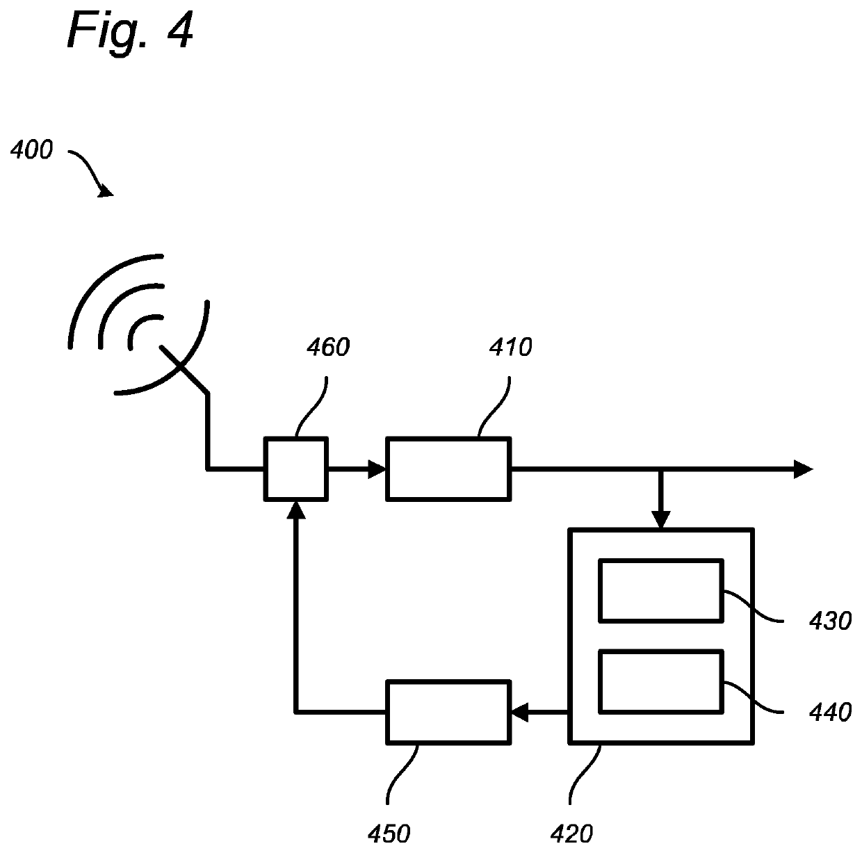
[0068]The present invention can be used to cancel an external disturbance in a received signal in a radar system feeding a correction signal to at least one channel of a radar which overcome or at least mitigate the problems of the prior art and with an improved functionality.

[0069]The invention is described in the following illustrative and non-limiting detailed description of exemplary embodiments, with reference to the appended drawings, wherein:

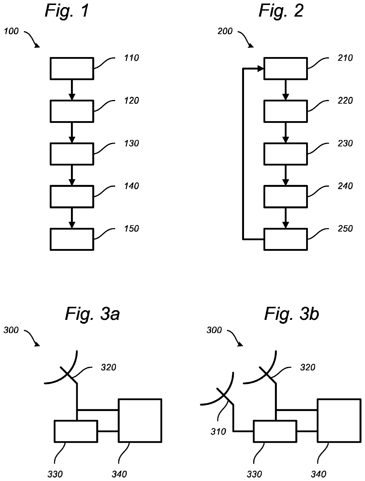
[0070]FIG. 1 shows a schematic illustration of a method 100 for operating a radar in a radar system to cancel an external disturbance in a received signal, according to an embodiment of the present invention. The method comprises receiving 110 a signal at a receiving antenna, wherein the signal comprises reflected signals and interfering signals, and receiving 120 from a receiving antenna, the signal at a control unit, wherein the signal is in the analogue domain. The method further comprise identifying 130 the interfering signal in a fre...


PUM


Abstract

A method for operating a radar in a radar system to cancel an external disturbance in a received signal is provided. The method comprises receiving a signal at the receiving antenna, receiving the signal at the control unit, identifying interfering signal, generating a correction signal and feeding the correction signal. The correction signal is arranged to dampen the interfering signal in the frequency span in the received signal. Thereby the external disturbance is reduced.

Description

TECHNICAL FIELD[0001]The present invention relates to methods for operating a radar system. The present invention further relates to a radar system for executing such methods and a program, a computer device readable medium carrying such a program and a control unit enabling that such methods are executed by the radar system.BACKGROUND ART[0002]The concept of radar was discovered late 19th century and was further developed during the first and second world wars where radars where used in order to detect e.g. hostile aircrafts. One example of radars are pulsed radars. A pulsed radar operates at two operation modes, a transmission mode where pulsed, high power radio frequency signals, referred to as transmission signals, are transmitted and a reception mode where the reflected echo of the transmitted transmission signals, which are referred to as reflection signals, reflected signals or reply signals, are received. The transmission signals are transmitted by means of transmission mean...

Claims


Application Information

Patent Timeline
Patent Type & Authority Applications(United States)
IPC IPC(8): G01S7/02G01S7/285G01S13/02
CPCG01S7/023G01S13/02G01S7/285G01S7/292H04B1/1027G01S7/36G01S7/0233G01S7/40
Inventor SILANDER, ANDERSANGUELOVA, MILENA
Owner SAAB AB
Learn More