
Banknote Conveying Module and Banknote Adding Machine Thereof

a technology of banknotes and modules, which is applied in the direction of coin/currency accepting devices, coins/paper handlers, instruments, etc., can solve the problems of increasing the purchase and management costs of financial institutions

Pending Publication Date: 2022-06-30
WEIRONG TECH CO LTD
View PDF0 Cites 0 Cited by
  • Summary
  • Abstract
  • Description
  • Claims
  • Application Information

AI Technical Summary

Benefits of technology

The present invention has a simple structure and small size, allowing for quick cash dispensing with one-by-one banknote adding. It also has easy removal and replacement of the cash box and allows for individual refueling of the banknote boxes. The lid lock unit is convenient for maintenance and the box door mechanism allows for easy opening and closing of the housing for easy loading and unloading of the case.

Problems solved by technology

However, for some small financial institutions, such flow line is too large, which can increase the purchase and management costs of the financial institution.

Method used


Image

  • Banknote Conveying Module and Banknote Adding Machine Thereof
  • Banknote Conveying Module and Banknote Adding Machine Thereof
  • Banknote Conveying Module and Banknote Adding Machine Thereof

Examples


Embodiment Construction

[0034]The technical solutions of the embodiments of the present invention will be described more fully hereinafter with reference to the accompanying drawings of embodiments of the invention.

[0035]In the description of the invention, it is to be understood that, the term “upper,”“lower,”“ front,”“rear,”“left,”“right,”“top,”“bottom,”“inner,”“outer,” etc., are based on the orientation or positional relationship shown in the figures, but are merely intended to facilitate the description of the present invention and the simplified description, rather than to indicate or imply that the indicated device or element must have a particular orientation, constructed and operative in a particular orientation, and therefore not to be construed as a limitation of the present invention.

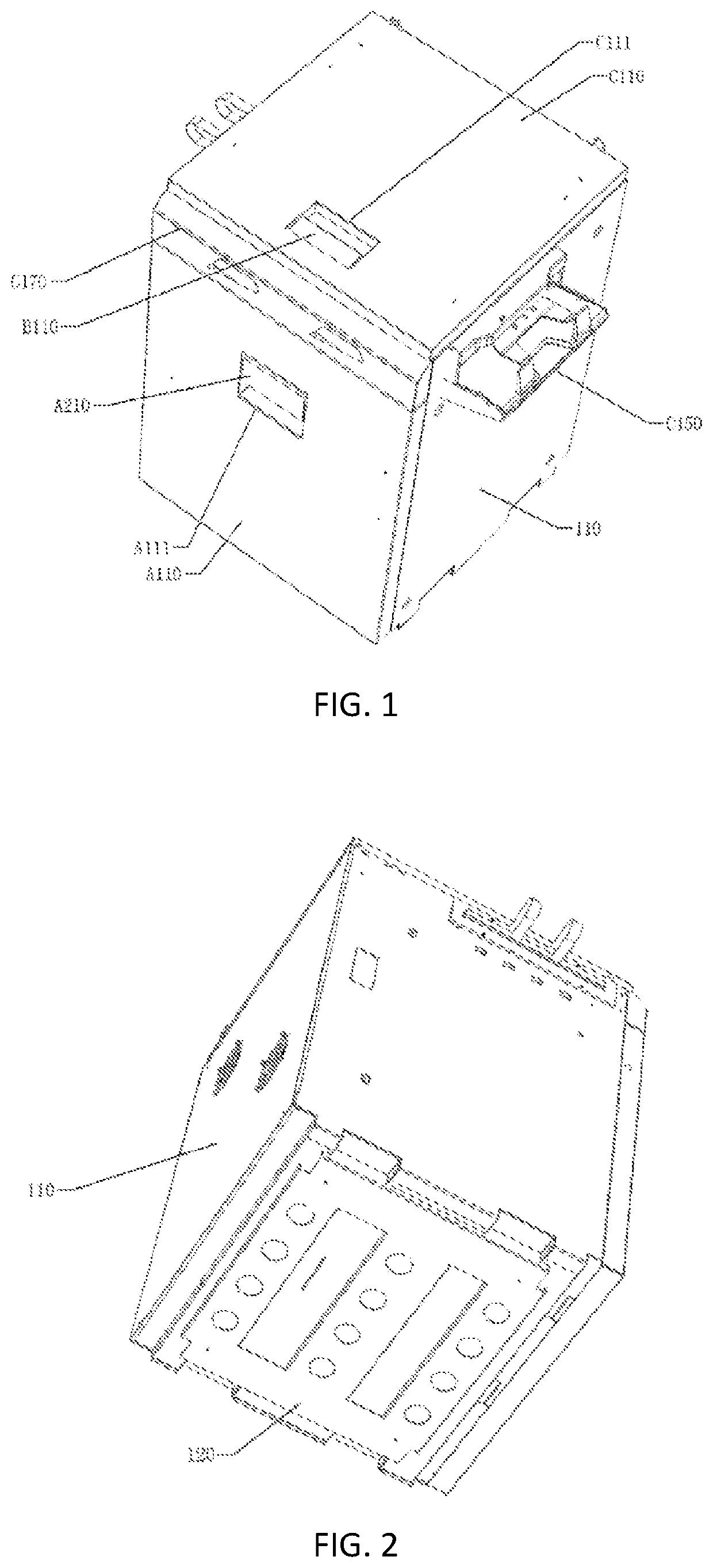
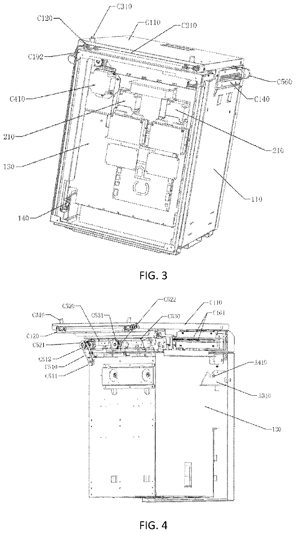
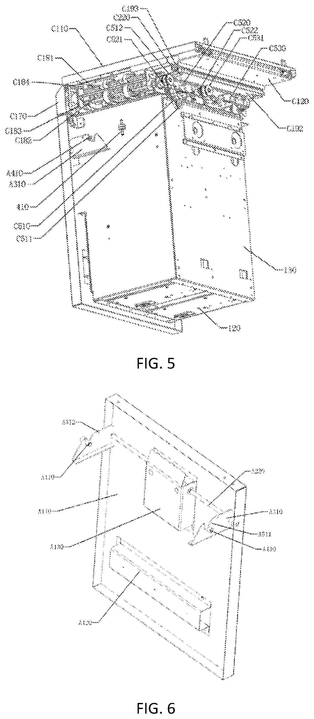
[0036]Referring to FIGS. 1-34, a banknote adding machine comprises a housing 110, wherein the housing 110 comprises an integrated box 130 mounted therein and has a side opening and a bottom wall 120 at a bottom of t...


PUM


Abstract

A banknote conveying module and a banknote adding machine thereof. The banknote conveying module comprises a lower banknote conveying plate (C182) and an upper banknote conveying plate (C181), a banknote conveying gap (C101) being formed between the upper banknote conveying plate (C181) and the lower banknote conveying plate (C182); an upper banknote conveying belt (C540) is mounted at the side in the banknote conveying gap (C101) close to the upper banknote conveying plate (C181), a lower banknote conveying belt (C550) is mounted at the side in the banknote conveying gap (C101) close to the lower banknote conveying plate (C182), and banknotes are clamped between the lower banknote conveying belt (C550) and the upper banknote conveying belt (C540) so as to be conveyed; each banknote box (500) corresponds to a group of a lower banknote conveying belt (C550), an upper banknote conveying belt (C540) and a reversing assembly, the reversing assembly comprises a reversing mounting plate (C710), the reversing mounting plate (C710) is fixed at the bottom of the lower banknote conveying plate (C182), and multiple reversing blocks (C740) are mounted and fixed above the reversing mounting plate (C710), the reversing blocks (C740) and two lower banknote conveying side plates (C183) are circumferentially and rotatably assembled by means of reversing shafts (C720), one end of each of the reversing shafts (C720) penetrates through one of the lower banknote conveying side plates (C183) and then is tangentially connected to a telescopic shaft of a reversing electromagnet (C420); and each of the reversing blocks (C740) is provided with a banknote feeding cambered surface (C741), a banknote passing planar surface (C742) and an stopping end (C743), and a banknote feeding guide plate (C730) is mounted at the lower banknote conveying plate (C182) at a corresponding position.

Description

BACKGROUND OF THE PRESENT INVENTIONField of Invention[0001]The present invention relates to financial equipment, and more particularly, to a banknote conveying module and banknote adding machine thereof.Description of Related Arts[0002]The financial institution typically needs to store the bills in an independent cash box during the banknote dispensing process, and then, money is deposited in the cash box, thereby facilitating the transportation of the banknotes. However, the depositing of banknote into the cash box mostly through a large and independent banknote distribution flow line, and such arrangement is mainly utilized for a large amount of banknote distribution. However, for some small financial institutions, such flow line is too large, which can increase the purchase and management costs of the financial institution.[0003]Therefore, a banknote conveying module and banknote adding machine thereof is designed, which banknote adding machine is small in size and capable of aut...

Claims


Application Information

Patent Timeline
Patent Type & Authority Applications(United States)
IPC IPC(8): G07D11/12G07D11/00
CPCG07D11/12G07D11/009G07D11/10
Inventor WEI, WEIFANG, ZHENCHEN, DEBEIGUAN, WEICAI, YAOZHUNNI, BATAOLI, RONGHAIWEI, XIAOLANWANG, MAOXING
Owner WEIRONG TECH CO LTD
Learn More