Eureka AIR delivers breakthrough ideas for toughest innovation challenges, trusted by R&D personnel around the world.

Heat exchanger, method of manufacturing the same, and air-conditioning apparatus

Pending Publication Date: 2022-06-23
MITSUBISHI ELECTRIC CORP
View PDF0 Cites 0 Cited by
  • Summary
  • Abstract
  • Description
  • Claims
  • Application Information

AI Technical Summary

Benefits of technology

The patent text describes a new design for heat exchangers that reduces the likelihood of damage to fins and headers during bending. The design eliminates the need for a stress-absorbing part in the bending target portion, reduces the likelihood of interference between headers, and avoids a complicated operation and an increase in steps for manufacture. Overall, this design prevents damage to the headers and fins, and improves heat exchange efficiency.

Problems solved by technology

In this case, compression or tension in bending the heat exchanger may cause fins located at inner part of a bending target portion of the heat exchanger to be collapsed or cause fins located at outer part of the bending target portion to be separated from the flat tubes, leading to a reduction in heat exchange efficiency.

Method used


Image

  • Heat exchanger, method of manufacturing the same, and air-conditioning apparatus
  • Heat exchanger, method of manufacturing the same, and air-conditioning apparatus
  • Heat exchanger, method of manufacturing the same, and air-conditioning apparatus

Examples


embodiment 1

200>

[0031]An air-conditioning apparatus according to Embodiment 1 will be described first. FIG. 1 is a refrigerant circuit diagram illustrating an example of an air-conditioning apparatus 200 according to Embodiment 1. In FIG. 1, solid-line outlined arrows represent the flow of refrigerant in a cooling operation, and broken-line outlined arrows represent the flow of the refrigerant in a heating operation.

[0032]As illustrated in FIG. 1, the air-conditioning apparatus 200 includes an outdoor unit 201 and an indoor unit 202. The outdoor unit 201 includes a heat exchanger 10, used as an outdoor heat exchanger, an outdoor fan 13, a compressor 14, and a four-way valve 15. The indoor unit 202 includes an indoor heat exchanger 16, an expansion device 17, and an indoor fan (not illustrated). The heat exchanger 10, the compressor 14, the four-way valve 15, the indoor heat exchanger 16, and the expansion device 17 are connected by refrigerant pipes 12, thus forming a refrigerant circuit.

[0033]...

embodiment 2

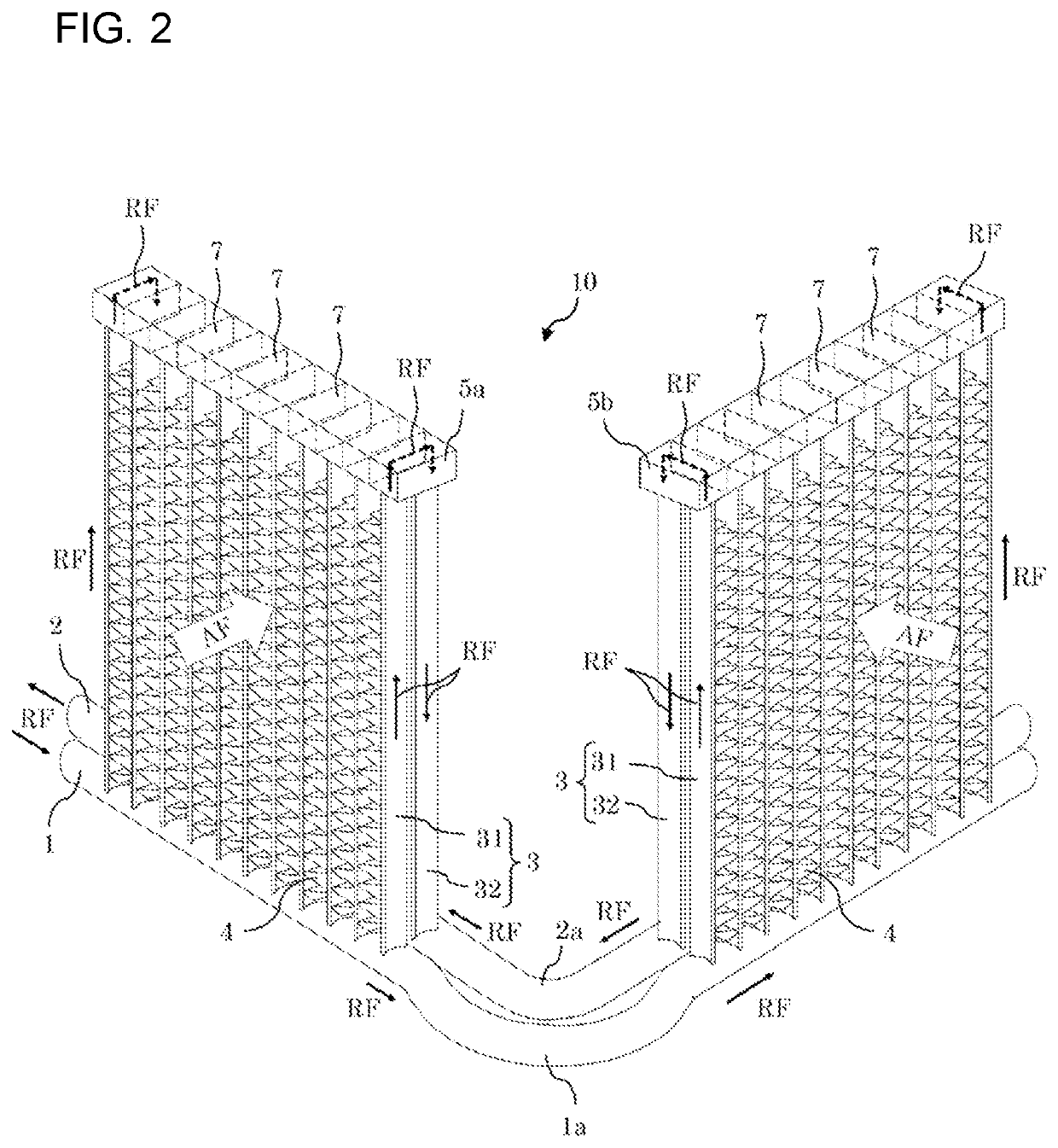
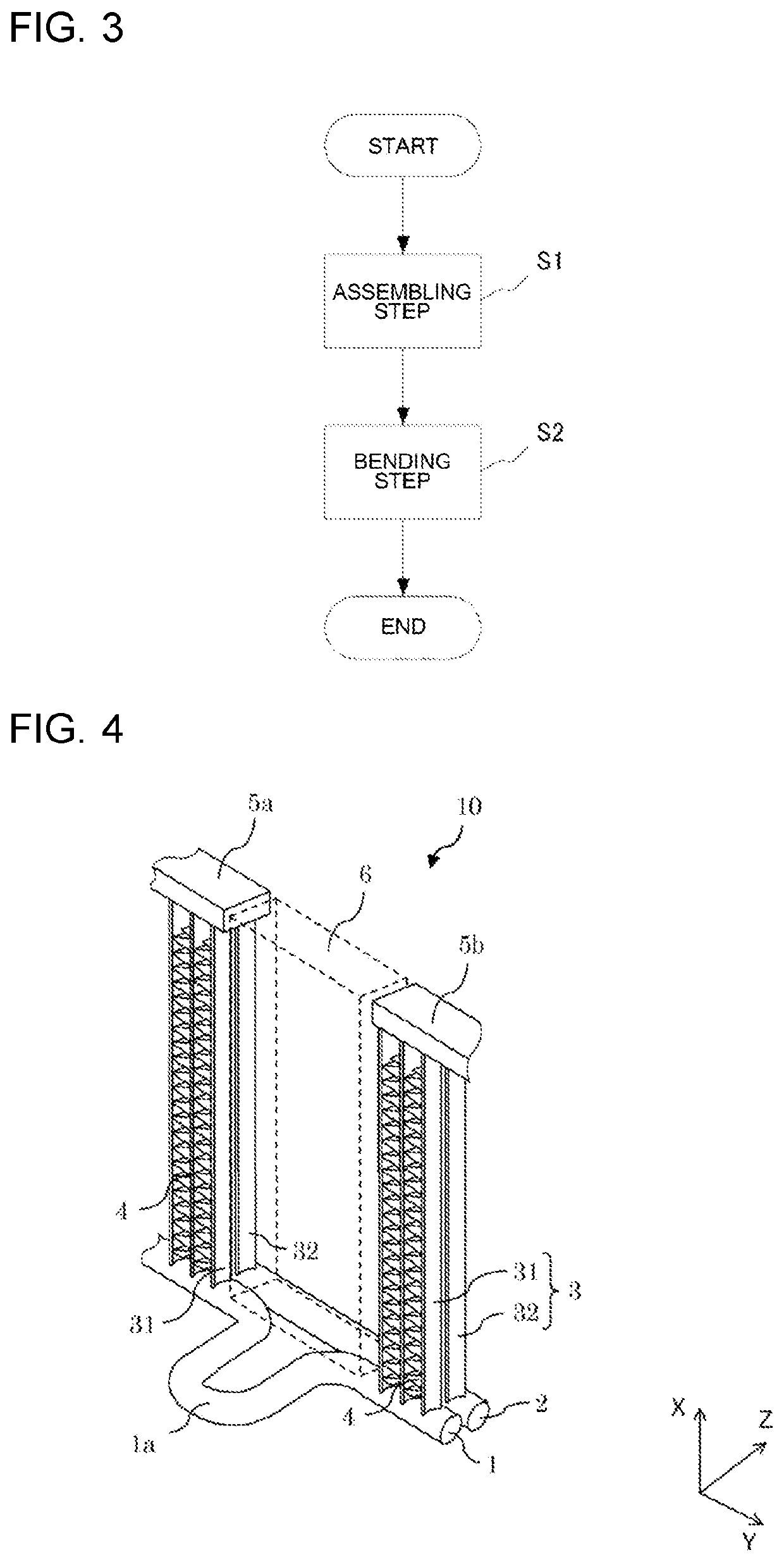
[0067]A heat exchanger 10 according to Embodiment 2 of the present disclosure will be described below. FIG. 6 is a perspective view of the heat exchanger 10 according to Embodiment 2 in the pre-bending state. FIG. 7 is a perspective view of the heat exchanger 10 according to Embodiment 2 in the post-bending state.

[0068]In Embodiment 2, the first header 1 in Embodiment 1 is partly modified. The heat exchanger 10 and an air-conditioning apparatus 200 in Embodiment 2 have the same configurations as those in Embodiment 1, and explanation of the configurations is omitted. The same components or equivalents are designated by the same reference signs.

[0069]For the stress-absorbing part 1a of the heat exchanger 10 according to Embodiment 2, as illustrated in FIGS. 6 and 7, the stress-absorbing part 1a of the first header 1 is curved in the first direction X. Specifically, the stress-absorbing part 1a of the first header 1 in Embodiment 2 is curved toward the third headers 5a and 5b, or upwa...

embodiment 3

[0072]A heat exchanger 10 according to Embodiment 3 of the present disclosure will be described below. FIG. 8 is a plan view of the heat exchanger 10 according to Embodiment 3 in the pre-bending state.

[0073]In Embodiment 3, the first header 1 in Embodiment 1 is partly modified. The heat exchanger 10 and an air-conditioning apparatus 200 in Embodiment 3 have the same configurations as those in Embodiment 1, and explanation of the configurations is omitted. The same components or equivalents are designated by the same reference signs.

[0074]In Embodiment 3, as illustrated in FIG. 8, the first header 1 of the heat exchanger 10 includes two segments located on opposite sides of the bending target portion 6 (refer to FIG. 4). The stress-absorbing part 1a is a separate coupling that couples facing ends of the segments of the first header 1, or a first end 1b and a second end 1c. In this case, the first and second ends 1b and 1c of the first header 1, the stress-absorbing part 1a, which is ...


PUM


Abstract

A heat exchanger includes a first row of flat tubes, a second row of flat tubes, a first header causing first ends of the flat tubes in the first row in a first direction to communicate with each other, a second header causing first ends of the flat tubes in the second row in the first direction to communicate with each other, and a third header that causes the second ends to communicate with each other and connects the first and second rows to cause refrigerant to flow between the first header and the second header. The flat tubes are arranged outside a space between the segments of the third header. A stress-absorbing part is provided in at least a bending target portion of one of the first header and the second header subjected to larger stress from the bending than the other one of the first header and the second header.

Description

TECHNICAL FIELD[0001]The present disclosure relates to a heat exchanger, a method of manufacturing the same, and an air-conditioning apparatus.BACKGROUND ART[0002]A heat exchanger that is mounted in an indoor unit of an air-conditioning apparatus and operates as a condenser and a heat exchanger that is mounted in an outdoor unit and operates as an evaporator in the air-conditioning apparatus are known. Liquid refrigerant that is condensed in the heat exchanger in the indoor unit is reduced in pressure by an expansion valve and thus turns into a two-phase gas-liquid state, which is a mixture of gas refrigerant and liquid refrigerant. The heat exchanger in the outdoor unit evaporates the liquid refrigerant included in the two-phase gas-liquid refrigerant, so that the two-phase gas-liquid refrigerant turns into low-pressure gas refrigerant. After that, the low-pressure gas refrigerant leaving this heat exchanger enters a compressor mounted in the outdoor unit. The refrigerant is compre...

Claims


Application Information

Patent Timeline
IPC IPC(8): F28F9/02F24F1/18F25B39/04F25B39/02F28D1/053
CPCF28F9/02F24F1/18F28D1/053F25B39/022F25B39/04F28D1/05391F28D1/0443F28F9/0248F25B13/00
Inventor NAKAMURA, MASASHIOKADA, MASAKIKAWABATA, RYOHEI
Owner MITSUBISHI ELECTRIC CORP
Why Eureka
Eureka Blog
Learn More