Eureka AIR delivers breakthrough ideas for toughest innovation challenges, trusted by R&D personnel around the world.

Magnetic latch for fastening a hinged closure member to a support

a technology of hinged closure and magnetized latch, which is applied in the direction of wing fasteners, non-mechanical controls, construction fastening devices, etc., can solve the problems of difficult execution for users, difficult positioning of latch bolt mechanism, and difficulty in opening. a series of complicated motions

Pending Publication Date: 2022-05-12
LOCINOX NV
View PDF11 Cites 2 Cited by
  • Summary
  • Abstract
  • Description
  • Claims
  • Application Information

AI Technical Summary

Benefits of technology

The patent describes a mechanism for a latch bolt assembly that uses magnets to provide a stronger magnetic attraction. This allows for the latch bolt to be magnetically attracted from a further distance with greater force. This increases the leeway between the position of the keeper assembly and the latch assembly, avoiding any sagging or movement of the closure member. The increased magnetic attraction also results in a reduction of the force required to unfasten the closure member. In a more preferred embodiment, the locking member engages the driving part to lock it in its rest position. This provides a well-balanced system and minimizes potential torque-related effects that could be caused by exerting forces on opposing sides of the frame.

Problems solved by technology

A downside of such improved safety measures is that the opening requires a series of complicated motions which may be difficult for a user to execute.
A downside of these locking mechanism is that the latch bolt mechanism is positioned quite low and may be in reach of children.
This may pose a danger in case a user locks the locking mechanism while the gate is opened as this may prevent the latch bolt from entering the keeper and thus leave the gate unfastened.
General downsides of the first kind of magnetic latch assemblies is that the distance between the gate and the support is crucial.
As such, a careful height and width placement are required which is time consuming.
Consequently, when the gate sags or otherwise moves somewhat, the distance between the permanent magnet and the latch bolt will become immediately so great that the magnetic attraction will no longer be able to attract the latch bolt against the tension of the compression spring and the gate will thus no longer be latched.
Another downside is that the knob may be difficult to lift.
More specifically, the force required to lift the knob in combination with the height at which the knob is positioned may make it difficult for a user (in particular a user of low height) to unfasten the closure member.
Another downside is that the magnet and the latch bolt are unlocked in a sideways fashion.
A downside of the mounting assembly is that height adjustments require removing the housing from the closure system and reattaching it at a different height.
This is a time-consuming operation as all transverse bolts need to be unfastened and fastened again.
A downside of this locking mechanism is that the locking mechanism is used to lock the latch bar in its latching position.
This may pose a danger in case a user locks the locking mechanism while the gate is opened as this may prevent the latch bolt from entering the keeper and thus leave the gate unfastened.
A drawback of the second kind of magnetic latch assemblies is that a person who wants to open the gate has to have both hands free as he has to pull the bolt of the latching device with one of his hands upward and at the same time he has to open the gate with his other hand.
A further drawback of this known latching device is that the keeper assembly has to be positioned perfectly underneath the latch bolt in order to be able to draw the latch bolt by magnetic attraction into the retaining element.
Consequently, when the gate sags or otherwise moves somewhat, the distance between the permanent magnet and the latch bolt will become immediately so great that the magnetic attraction will no longer be able to attract the latch bolt against the tension of the compression spring and the gate will thus no longer be latched.
Another drawback of the second kind of magnetic latch assemblies is that the key cylinder is placed adjacent the link bar and knob so the latch bolt assembly becomes rather bulky.

Method used


Image

  • Magnetic latch for fastening a hinged closure member to a support
  • Magnetic latch for fastening a hinged closure member to a support
  • Magnetic latch for fastening a hinged closure member to a support

Examples


Embodiment Construction

[0073]The present invention will be described with respect to particular embodiments and with reference to certain drawings but the invention is not limited thereto but only by the claims. The drawings described are only schematic and are non-limiting. In the drawings, the size of some of the elements may be exaggerated and not drawn on scale for illustrative purposes. The dimensions and the relative dimensions do not necessarily correspond to actual reductions to practice of the invention.

[0074]Furthermore, the terms first, second, third and the like in the description and in the claims, are used for distinguishing between similar elements and not necessarily for describing a sequential or chronological order. The terms are interchangeable under appropriate circumstances and the embodiments of the invention can operate in other sequences than described or illustrated herein.

[0075]Moreover, the various embodiments, although referred to as “preferred” are to be construed as exemplary...


PUM


Abstract

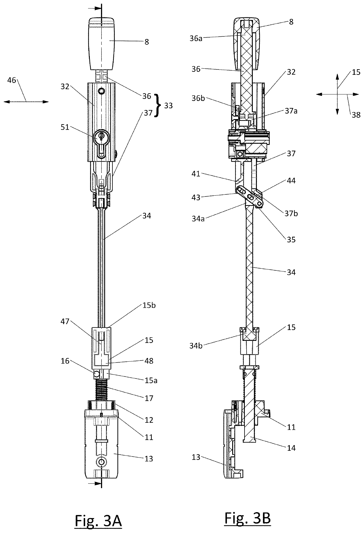
A magnetic latch for fastening a closure member to a support. The magnetic latch comprises a keeper assembly including a magnet and a latch bolt assembly having: an elongated frame (32); a latch bolt (14) moveable between a latching position and a retracted position; a latch bolt biasing member urging the latch bolt into its retracted position; and a latch bolt operating mechanism configured to move the latch bolt from its latching position to its retracted position against a magnetic attraction. The latch bolt operating mechanism comprises: an effort link rod (37); a load link rod (34); and a second-order lever (35) interposed between the effort link rod and the load link rod. The second-order lever reduces the force required to operate the latch bolt operating mechanism thus allowing for an increased magnetic attraction of the latch bolt towards the magnet in the keeper assembly.

Description

TECHNICAL FIELD[0001]The present invention relates to a magnetic latch for fastening a hinged closure member to a support.BACKGROUND ART[0002]A magnetic latch assembly comprises a latch bolt assembly configured to be mounted to one of the hinged closure member and the support and a magnet keeper assembly configured to be mounted to the other one of the hinged closure member and the support. The magnetic latch assembly can be mounted on various types of closure members, in particular a door or a gate. In several countries there are legal regulations for swimming pool gates. Most of these regulations specify a minimum height for the safety gates, a minimum height at which the actuator for opening the closure member are to be located, and / or required minimal and / or maximal force required to actuate the actuator. A common way to meet these requirements is by mounting the latch bolt assembly in an upright position on top of the gate with the actuator on the upper side of the latch bolt a...

Claims


Application Information

Patent Timeline
Patent Type & Authority Applications(United States)
IPC IPC(8): E05B47/00E05C1/00E05C1/08E05C1/10
CPCE05B47/004E05C1/10E05C1/085E05C1/004E05C19/163E05C19/168E05B65/0007E05B53/00E05C1/006E05C1/166
Inventor TALPE, JOSEPH
Owner LOCINOX NV
Why Eureka
Eureka Blog
Learn More