
Razor cartridge

a technology of razor and shavers, applied in the field of razor cartridges, can solve the problems of prolonging the life of shavers, and achieve the effects of reducing the occurrence of nicks and cuts, enhancing the control of skin pressure, and increasing surface area

Pending Publication Date: 2022-04-21
BIC VIOLEX SA
View PDF0 Cites 2 Cited by
  • Summary
  • Abstract
  • Description
  • Claims
  • Application Information

AI Technical Summary

Benefits of technology

The patent is about a shaving head that reduces the likelihood of nicks and cuts during shaving. By mounting the cutting element on the support facing away from the shaving surface, additional contact points are created which increases the surface area the shaving force is applied. Additionally, by providing negative and positive cutting edge exposures, users can customize the shaving experience based on their needs and desires. This results in better shaving experiences for users with sensitive skin. The shaving head also allows for effective removal of shaving debris, reducing the need for rinsing and improving the overall shaving experience. The increased spacing between the blades and the user-friendly design also makes shaving strokes longer and reduces the need for rinsing.

Problems solved by technology

This extends lifetime of the shavers, particularly as banging of the shaver to dislodge debris may undesirably change blade exposure.

Method used


Image

  • Razor cartridge
  • Razor cartridge
  • Razor cartridge

Examples


Embodiment Construction

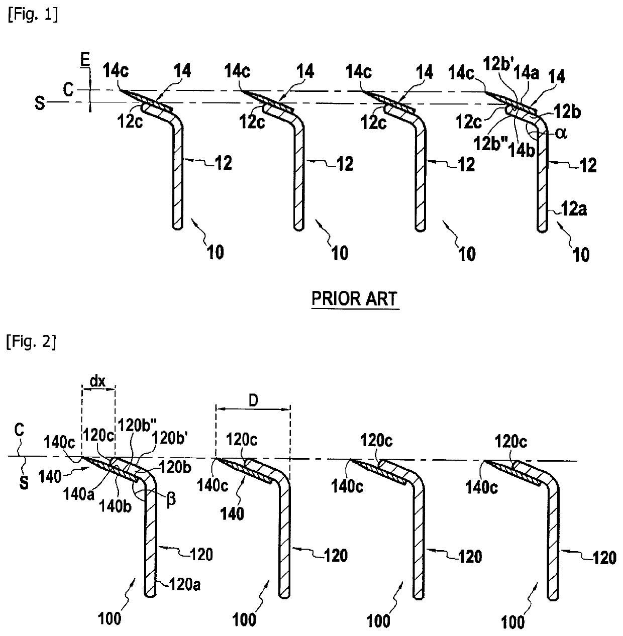
[0032]FIG. 1 shows a plurality of a conventional blade assemblies, each blade assembly 10 includes a blade support 12 and a blade 14.

[0033]The blade support 12 may include a base portion 12a and a flat portion 12b. The flat portion 12b may have a front end 12c. The flat portion 12b may extend at an angle α relative to the base portion 12a. The flat portion 12b may have an upper surface 12b′ and a lower surface 12b″ opposite the upper surface 12b′.

[0034]The blade 14 may include an upper surface 14a, a lower surface 14b opposite the upper surface 14a, and a cutting edge 14c. The lower surface 14b of the blade 14 may be attached to the upper surface 12b′ of the blade support 12.

[0035]Furthermore, a support plane S is defined by a tangent line to the front ends 12c of the blade supports. A cutting plane C is defined by a tangent line intersecting the cutting edges 14c of the blades 14. A cutting edge exposure E is defined as the vertical distance between the cutting plane C and the sup...


PUM


Abstract

A razor cartridge comprising a first blade support and a second blade support, each of the first and second blade supports include a flat portion having a lower surface and a front end. A support plane S is tangent to the respective front ends of the first and second blade supports and the lower surface faces away from the support plane S. A first blade is attached to the lower surface of the flat portion of the first blade support. The first blade includes a first cutting edge. A second blade is attached to the lower surface of the flat portion of the second blade support. The second blade includes a second cutting edge. The first and second cutting edges are offset with respect to the support plane S.

Description

CROSS-REFERENCE TO RELATED APPLICATION(S)[0001]This application is a National Stage Application of International Application No. PCT / EP2020 / 052166, filed on 29 Jan. 2020, now published as WO / 2020 / 157132, and which claims priority to European Patent Application No. EP 19154896.5, filed on 31 Jan. 2019, entitled “RAZOR CARTRIDGE”, the entire contents of which are incorporated herein by reference.BACKGROUND1. Field[0002]The following description relates to razor cartridges for a shaving devices, and more particularly to a razor cartridge having at least two blade assemblies that can have a positive or negative exposure relative to a support plane.2. Description of Related Art[0003]Shaving devices generally include a head unit having at least one or more cutting members or blades retained therein. The at least one or more cutting members or blades have cutting edges that are aligned in parallel when retained within the head unit.[0004]Conventional shaving heads include a blade mounted o...

Claims


Application Information

Patent Timeline
Patent Type & Authority Applications(United States)
IPC IPC(8): B26B21/40B26B21/56
CPCB26B21/4031B26B21/565
Inventor BOZIKIS, IOANNISGALANIS, CHRISTOSSCHIZAS, CHARALAMPOSAMPATIS, CHRISTOS
Owner BIC VIOLEX SA
Learn More