


Quick Research
Generate reliable direction feasibility study reports for your R&D in just a few steps.

Technical Q&A
Discover and master advanced knowledge NOW. Basics, ideas, possibilities, all at once.

Find Solutions
As an expert in R&D theories, this can generate solutions to your technical problems instantly.

Evaluate Feasibility
Analyze your overall solution with one click, know your potential R&D risks in advance.

Monitor Landscape
Get weekly tech updates, stay abreast of the latest tech innovations and key insights.
Modified Z Stents for Iliac Vein Stenting
a technology of iliac veins and stents, which is applied in the field of modified z stents for iliac vein stenting, can solve the problems of decreased fluid flow through the stent, increased post-thrombotic fibrosis, and stent deploymen
- Summary
- Abstract
- Description
- Claims
- Application Information
AI Technical Summary
Problems solved by technology
Method used
Image

Examples
first embodiment
st Suture
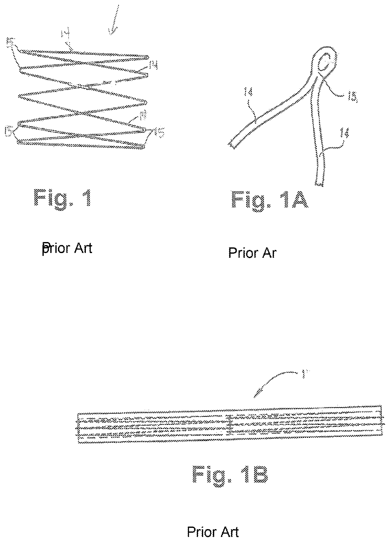
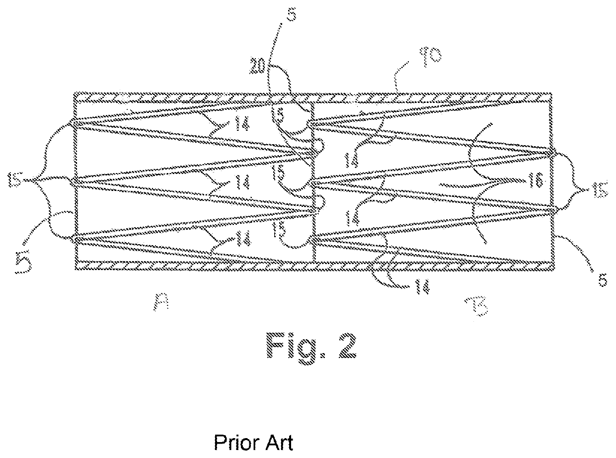
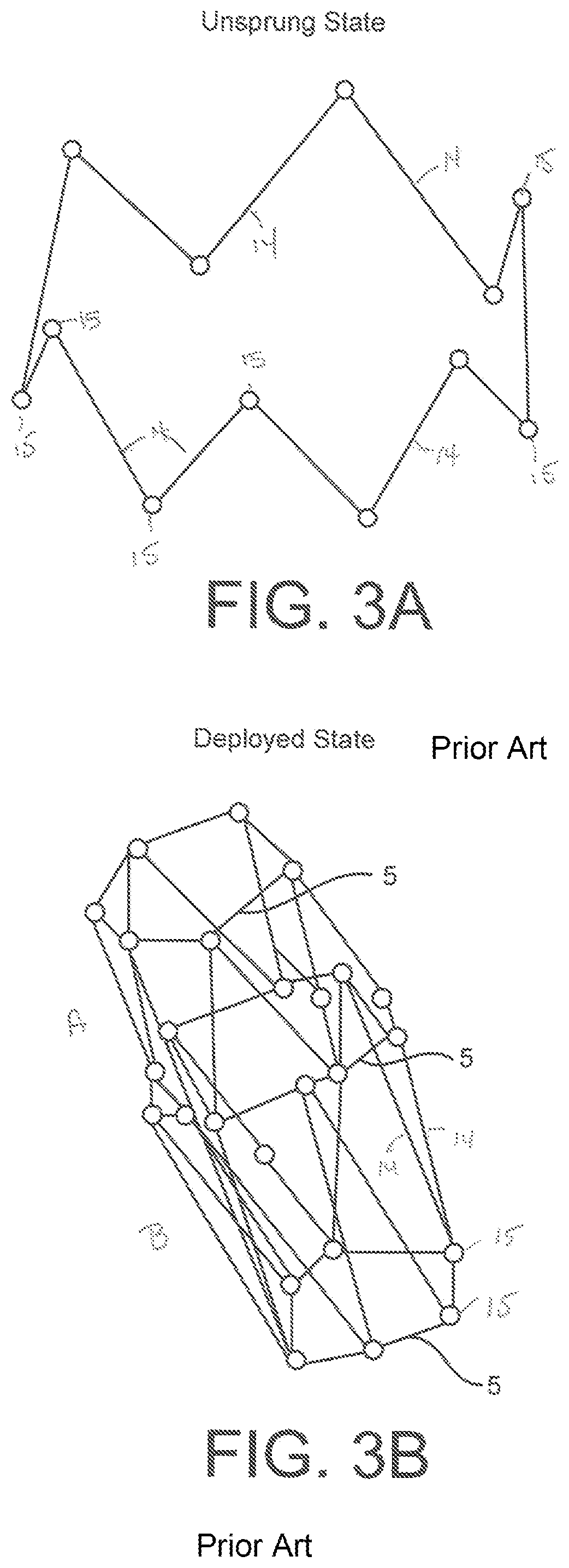
[0030]An intermediary waist suture 5M (a suture placed on each strut of the topmost Z stent cylinder at a point between the top and bottom of the struts (preferably positioned at a point where the intermediary waist stent 5M will extend into the vena cava). For a stent of length 2.5 cm, “midline sutures” are provided, positioned at about 1.25 cm from the top of the stent module or about halfway down the wall of lengths of the struts in the topmost stent. Such an intermediary suture is preferably placed in the uppermost stent, more preferably the upper and lower or bottom cylinder stents and most preferably in each strut of each cylinder in the stacked stent module. A suture 5 is also provided between each stacked cylinder to join the cylinders through the overlapping loops into a single integrated Z stent module. The upper cylinder A′s topmost suture 5 and optionally the lowermost cylinder's' bottommost sutures 5 in stent cylinder C, used in the prior art three-cylinder (or...
PUM
 Abstract
Description
Claims
Application Information
 - R&D Engineer
- R&D Manager
- IP Professional
- Industry Leading Data Capabilities
- Powerful AI technology
- Patent DNA Extraction
Browse by: Latest US Patents, China's latest patents, Technical Efficacy Thesaurus, Application Domain, Technology Topic, Popular Technical Reports.
© 2024 PatSnap. All rights reserved.Legal|Privacy policy|Modern Slavery Act Transparency Statement|Sitemap|About US| Contact US: help@patsnap.com