
Rotor Section With Attached Bearing Sleeves For Submersible Pump Motor

Pending Publication Date: 2022-03-24
BAKER HUGHES OILFIELD OPERATIONS LLC
View PDF6 Cites 0 Cited by
  • Summary
  • Abstract
  • Description
  • Claims
  • Application Information

AI Technical Summary

Benefits of technology

The patent describes a submersible well pump assembly motor with a stator and rotor sections that rotate to pump liquid. The motor includes a housing, a shaft, and a rotor stack with an end ring and an annular bearing sleeve. The rotor assembly is balanced and mounted onto the shaft before being energized to rotate the shaft. The technical effect of this design is a more efficient and reliable submersible well pump assembly motor that can withstand higher temperatures and pressures in the wellbore.

Problems solved by technology

It is possible for a balanced rotor section to have a slightly different axis of rotation than the shaft because of the annular clearance, causing vibration during operation.

Method used


Image

  • Rotor Section With Attached Bearing Sleeves For Submersible Pump Motor
  • Rotor Section With Attached Bearing Sleeves For Submersible Pump Motor
  • Rotor Section With Attached Bearing Sleeves For Submersible Pump Motor

Examples


Embodiment Construction

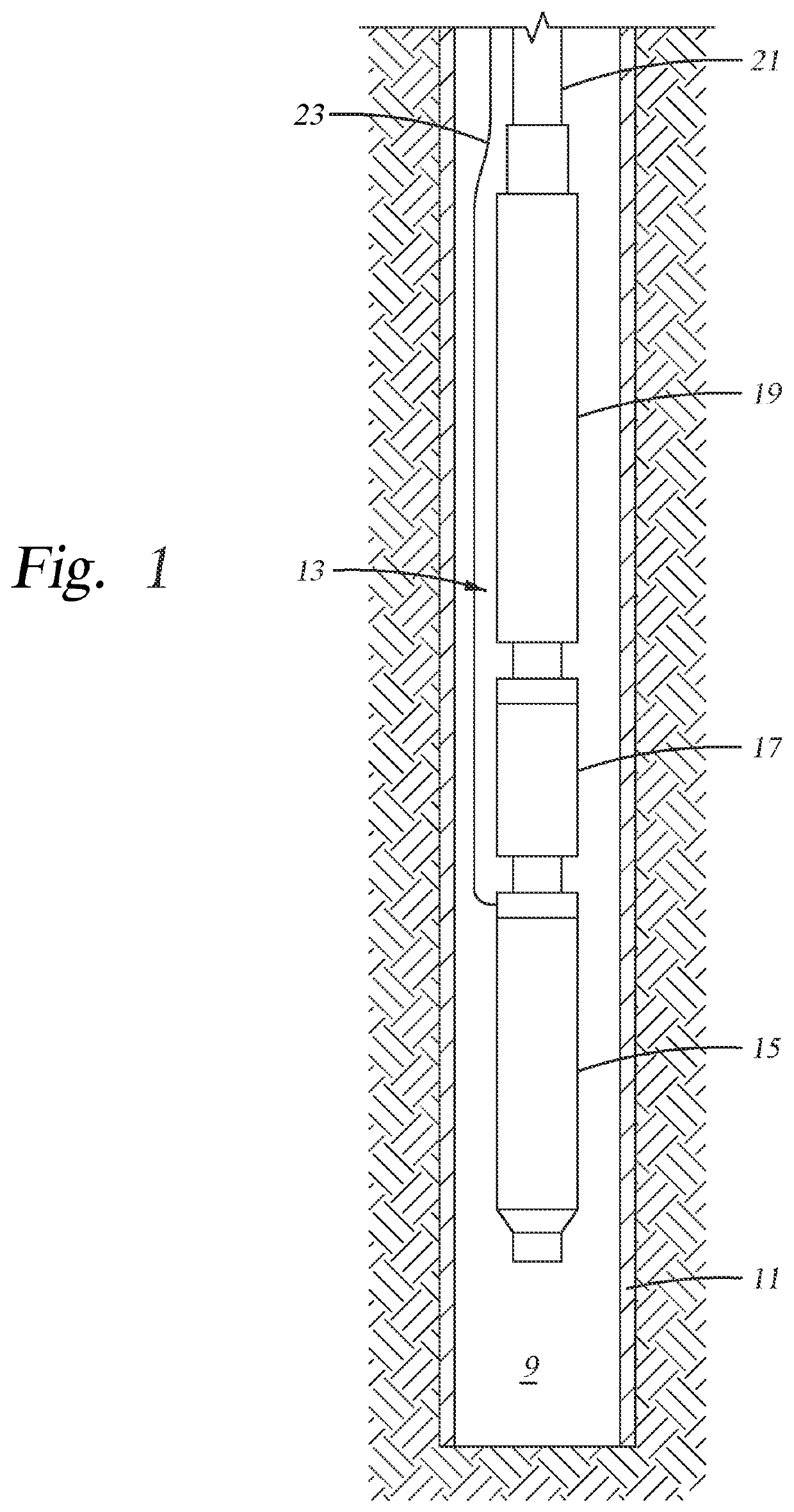
[0018]The method and system of the present disclosure will now be described more fully hereinafter with reference to the accompanying drawings in which embodiments are shown. The method and system of the present disclosure may be in many different forms and should not be construed as limited to the illustrated embodiments set forth herein; rather, these embodiments are provided so that this disclosure will be thorough and complete, and will fully convey its scope to those skilled in the art. Like numbers refer to like elements throughout. In an embodiment, usage of the term “about” includes + / −5% of a cited magnitude. In an embodiment, the term “substantially” includes + / −5% of a cited magnitude, comparison, or description. In an embodiment, usage of the term “generally” includes + / −10% of a cited magnitude.

[0019]It is to be further understood that the scope of the present disclosure is not limited to the exact details of construction, operation, exact materials, or embodiments show...


PUM


Abstract

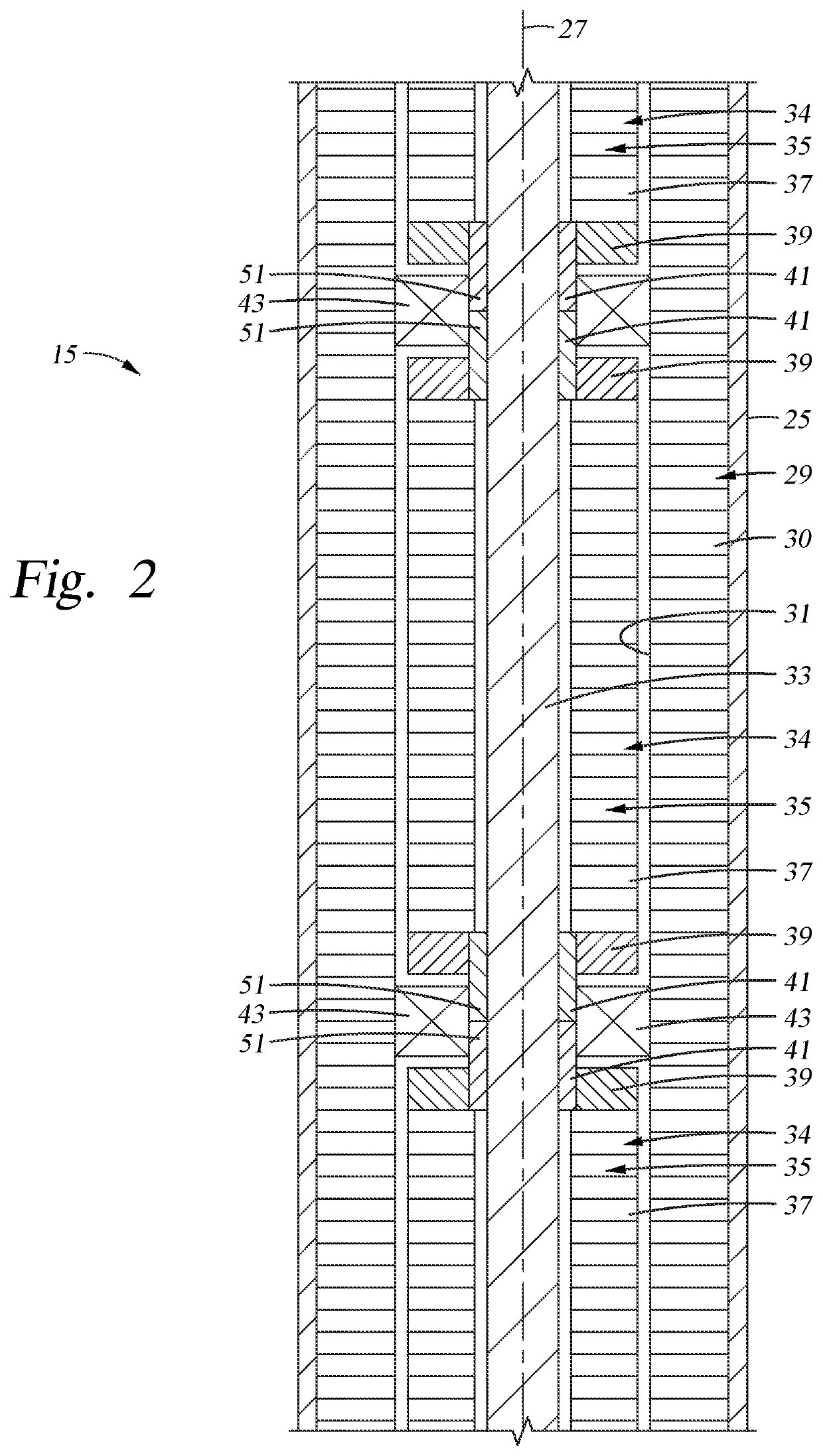
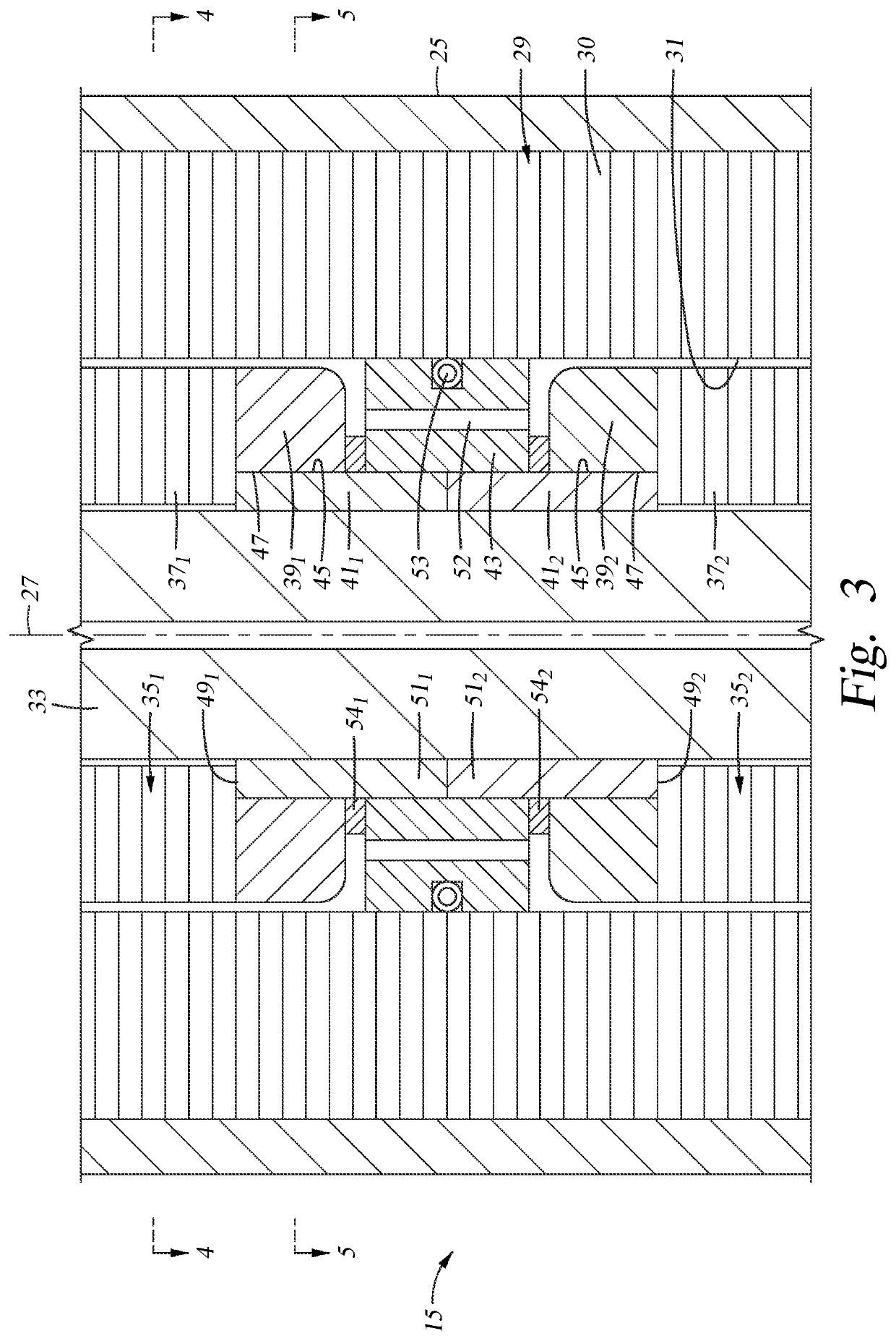
A submersible well pump assembly having a motor with a shaft, a stator, a rotor coupled to the shaft, and bearing sleeves between the shaft and a bearing assembly. The rotor includes a number of rotor sections located along an axis of the shaft, where each rotor section includes a stack of rotor disks and end rings on each end of the stack. Each bearing sleeve attaches to an end ring and extends axially away from the end ring into abutment with an end of another bearing sleeve attached to an adjacent end ring.

Description

CROSS-REFERENCE TO RELATED APPLICATION[0001]This application claims priority from U.S. Provisional Application Ser. No. 63 / 081,439, filed Sep. 22, 2020, the full disclosures of which are incorporated by reference herein in their entireties and for all purposes.BACKGROUND OF THE INVENTION1. Field of Invention[0002]The present disclosure relates in general to electrical submersible well pumps (ESP) and in particular to an ESP motor with rotor sections having bearing sleeves attached to opposite ends.2. Description of Prior Art[0003]Electrical submersible pump assemblies (“ESP”) are commonly used to pump well fluid from hydrocarbon producing wells. A typical ESP has a rotary pump driven by an electrical motor. The motor is filled with a dielectric motor oil. A pressure equalizer couples to the motor to reduce a pressure differential between the motor oil and the hydrostatic pressure of the well fluid.[0004]The motor has a stator with windings that are normally configured in a three-pha...

Claims


Application Information

Patent Timeline
IPC IPC(8): F04D13/10F04D13/08
CPCF04D13/10F04D13/086F04D29/047H02K5/167H02K5/132
Inventor FORSBERG, MICHAEL
Owner BAKER HUGHES OILFIELD OPERATIONS LLC
Learn More