Cam Lock Fitting With Vent and Safety Lock

a cam lock and safety lock technology, applied in the direction of couplings, mechanical equipment, etc., can solve the problems of unwelcome release of materials into the environment, injury to the operator, etc., and achieve the effect of preventing inadvertent pressure discharge and easy alignment of the cam lobes

Active Publication Date: 2022-03-10
HARTMAN JEFFREY +1
View PDF0 Cites 2 Cited by
  • Summary
  • Abstract
  • Description
  • Claims
  • Application Information

AI Technical Summary

Benefits of technology

[0006]The present invention discloses a cam lock fitting having an air vent and possibly a rotating female portion and includes a safety lock assembly for the cam lock fitting so that when the cam lock fitting is pressurized unbeknownst to the operator and the operator attempts to open the cam lock fitting the safety lock assembly will prevent operation or complete separation of the male and the female portions of the fitting to prevent inadvertent pressurized discharge of the dangerous materials. Rotation of the female portion is accomplished by placing a connecting collar member on the female end portion so that the female portion rotates abou

Problems solved by technology

A major problem sought to be solved by the present invention occurs at the time an operator of a conventional prior art cam lock fitting undertakes the operation of opening the fitting; at that time, the operator may not know whether the contents of the co

Method used


Image

  • Cam Lock Fitting With Vent and Safety Lock
  • Cam Lock Fitting With Vent and Safety Lock
  • Cam Lock Fitting With Vent and Safety Lock

Examples


embodiment 48

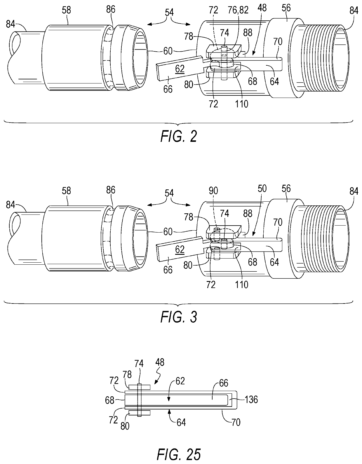
[0230]Turning to FIG. 2, therein is shown the embodiment 48 having a pair of double cam levers or members 62, 64 mounted on opposite sides of the female end portion 56 wherein each pair has an outer cam lever 62 and an inner cam lever 64. Outer cam lever 62 has a lever portion 66 and an eccentric cam lobe portion 68, and, inner cam lever 64 also has a lever portion 70 and first and second eccentric cam lobe portion 72 wherein the first and second cam lobe portions form the two prongs of a fork shaped portion being spaced apart a distance thereby creating a cutout or space 110 sufficient to allow the cam lobe portion 68 to fit therein between the two prongs which causes the inner and outer cam levers 62, 64 to be disposed symmetrically about the female end portion 56 which assures smooth operation throughout the life span of a cam lock fitting 54 made according to the teachings of the present invention. The cam lobe portion 72 resembles a fork shape when viewed from the top (see FIG....

first embodiment

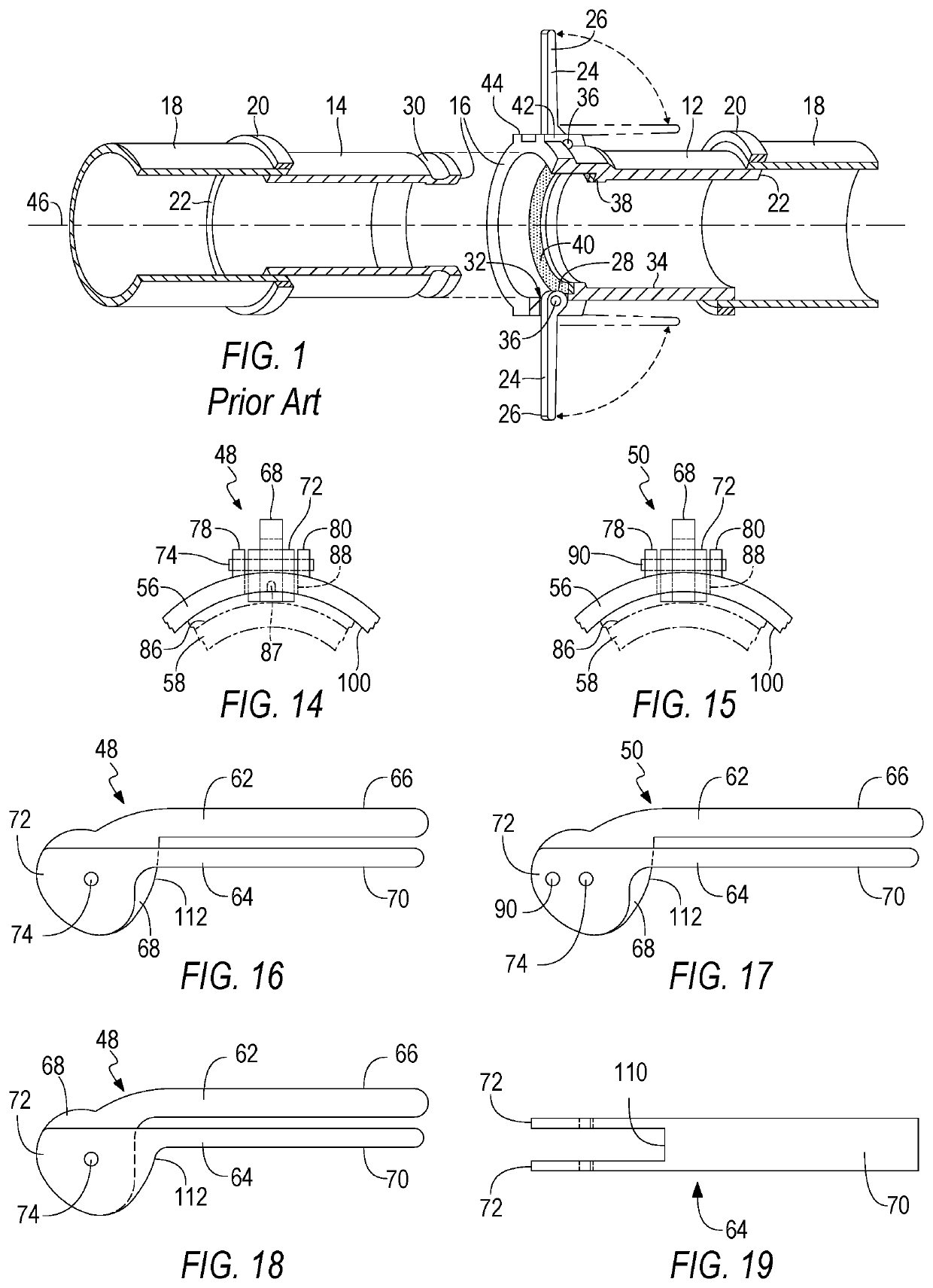
[0242]Turning to FIG. 19, therein is shown a top view of the inner cam lever 64 of the present invention showing previously disclosed elements. Space / cutout 110 between the prongs of the forked ends of the cam lobe portions 72 is also shown. It can be seen that the cam lobe portions 72 form the prongs of the forked portion.

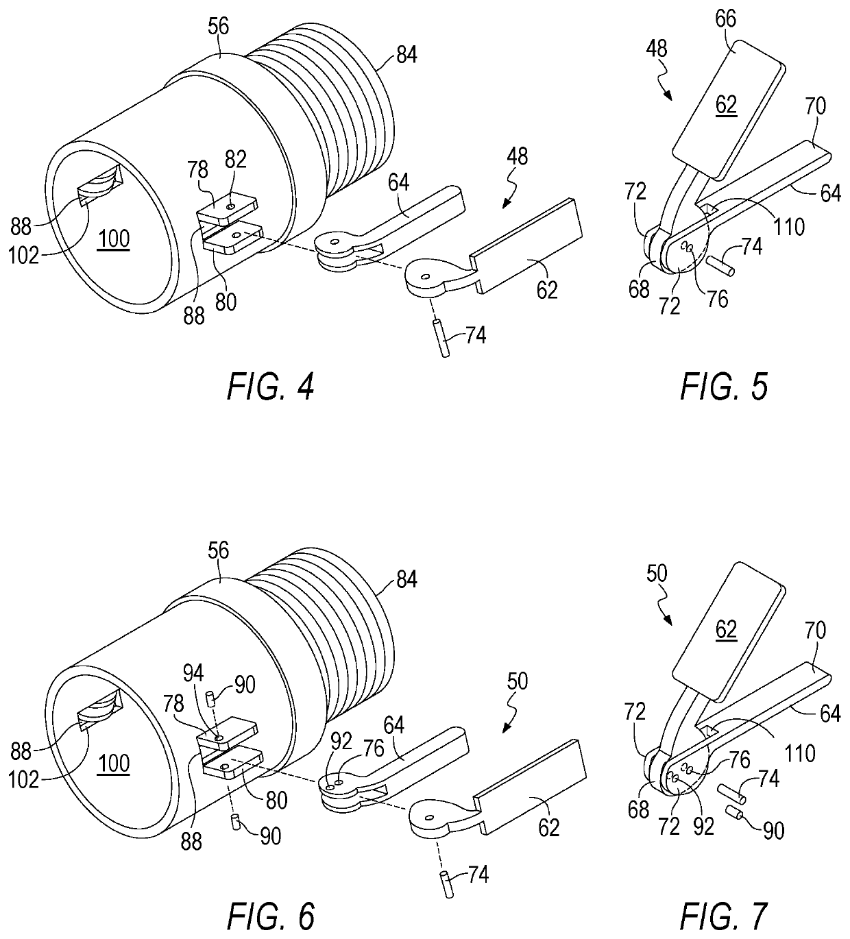
[0243]With reference to embodiments 48, 50 and 52, the cam members 62, 64 pivot substantially in a vertical plane passing through the centerline of the cam lock fitting / coupling 54 with the axles 74, 90 being substantially perpendicular to the centerline, and, the cam members are disposed on the bosses 78, 80 so that the cam lobes 68, 72, 96 and the axles will be properly operationally aligned with the groove 86 as required by each embodiment 48, 50, 52 all of which would be understood by one skilled in the art. The axles 74, 90 may be solid or hollow pins, roll pins or the like. Cam members 62, 64 are disposed substantially 180 degrees apart on opposite sides of ...

embodiment 50

[0250]Turning to FIG. 22, therein is shown the embodiment 50 which has been previously disclosed in relation to FIG. 7 of the present invention 10 shown in combination with the previously disclosed lever latching mechanism 113.

[0251]Turning to FIGS. 22-24, therein are shown partially cut-away side views of the present invention 10 showing pull rings 114 disposed on respective levers 62, 64 being attached through an aperture 120 in the end of respective pins 118 also showing the housing 122 along with the biasing spring 132, or the like, wherein the tips 124 of the pin are shown along with the inclined surface 126 and respective retaining protrusions 128, 130 disposed on boss 78. FIG. 23 shows the levers 62, 64 in a closed position similar to FIG. 8, and, FIG. 24 shows the levers 62, 64 in an open position similar to FIG. 10 wherein the pull rings 114 of the levers 62, 64 have been operated and moved by a finger 134 of an operator / user so that the tips of the pin 124 are no longer ca...


PUM


Abstract

A method and apparatus for an improved rotatable safety cam lock fitting with an air vent, the male and female portions of the cam lock fitting only slightly separate from each other allowing the operator to reclose the cam lock fitting if the operator observes that the cam lock fitting still contains pressurized material. Rotation of the female portion is accomplished by placing a connecting collar on the rear of the female end portion so that the female portion rotates about the connecting collar. The safety lock mechanism operates by placing opposing notches in the end of the male portion so that when the cam levers are opened the male and female portions of the cam lock fitting initially only slightly separate allowing the operator to quickly reclose the cam lock fitting if it contains pressurized material. The rotating female portion easily aligns the cam lobes of the cam lever with the notches on the male coupling so that the male and female portions can be separated.

Description

BACKGROUND OF THE INVENTIONField of the Invention[0001]The present invention relates generally to cam lock fittings and, more particularly, is concerned with a rotatable cam lock fitting having a vent and safety lock assembly thereon.Description of the Related Art[0002]Cam lock fittings having double cam levers have been described in the related art, and, cam lock fittings having safety features have been described in the related art. However, none of the related art devices disclose the unique features of the present invention.[0003]U.S. Pat. No. 4,802,694 to Vargo, dated Feb. 7, 1989, disclosed a quick-disconnect coupling. However, in use the coupling of Vargo was plagued by the problem that its handles 64, 60 and 74, 68 could be inadvertently opened simultaneously by an operator, thus making it dangerous to use; this occurred because the handles were disposed in side-by-side relation as shown in FIGS. 2 and 4. The present invention overcomes this problem by requiring that the out...

Claims


Application Information

Patent Timeline
IPC IPC(8): F16L37/18
CPCF16L37/18
Inventor HARTMAN, JEFFREYWILLIAMSON, GEORGE L.
Owner HARTMAN JEFFREY
Why Eureka
Try Eureka