Hitch angle detection using automotive radar

Active Publication Date: 2022-03-03
FORD GLOBAL TECH LLC
View PDF11 Cites 1 Cited by
  • Summary
  • Abstract
  • Description
  • Claims
  • Application Information

AI Technical Summary

Benefits of technology

This patent describes a system and method for detecting the angle between a trailer and a vehicle using radar technology. The system includes a radar system that sends data to the rear of the vehicle, and a controller that processes the data and uses it to determine the angle between the trailer and the vehicle. This angle is important for safely attaching the trailer to the vehicle and ensuring proper connection. The system combines multiple object point location data sets to increase sensitivity and accuracy. The technical effect of this patent is to provide a reliable and efficient system for identifying the angle between a trailer and a vehicle using radar technology.

Problems solved by technology

Reversing a vehicle while towing a trailer can be challenging for many drivers, particularly for drivers that drive with a trailer on an infrequent basis or with various types of trailers.
While some systems have relied on user input for the trailer length, doing so may place an undesired burden on the user and may introduce inaccuracies that some such systems are unequipped to handle.

Method used


Image

  • Hitch angle detection using automotive radar
  • Hitch angle detection using automotive radar
  • Hitch angle detection using automotive radar

Examples


Embodiment Construction

[0037]Additional features and advantages of the presently disclosed device will be set forth in the detailed description which follows and will be apparent to those skilled in the art from the description, or recognized by practicing the device as described in the following description, together with the claims and appended drawings.

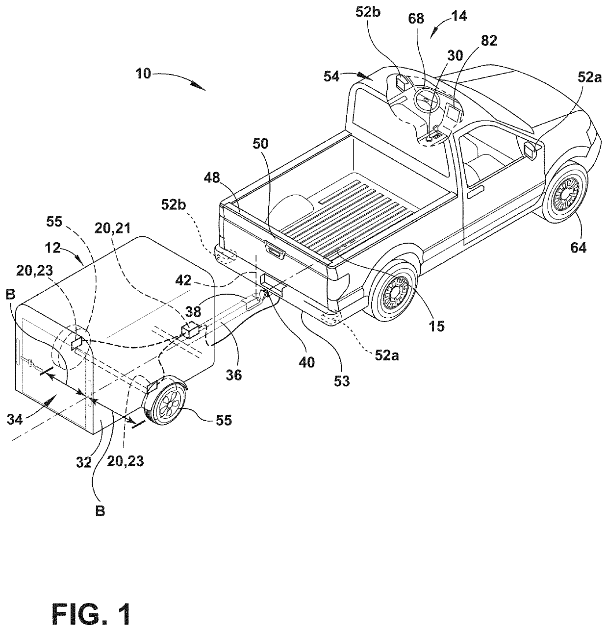
[0038]For purposes of description herein, the terms “upper,”“lower,”“right,”“left,”“rear,”“front,”“vertical,”“horizontal,”“interior,”“exterior,” and derivatives thereof shall relate to the disclosure as oriented in FIG. 1. However, it is to be understood that the disclosure may assume various alternative orientations and step sequences, except where expressly specified to the contrary. It is also to be understood that the specific devices and processes illustrated in the attached drawings, and described in the following specification are simply exemplary embodiments of the inventive concepts defined in the appended claims. Hence, specific dimensions and ...


PUM


Abstract

A vehicle trailer detection system includes a radar system and a controller receiving object point location data from the radar system at an increased sensitivity level, storing sequential first and second object point location data sets, and applying a rotational point set registration to the first and second object point location data sets to achieve a match between a subset of persistent point locations within the first and second object point location data sets to output an estimated rotation angle. The persistent point locations in the first and second data sets are determined to correspond with detected points on a trailer coupled with the vehicle. The controller refines the estimated rotation angle by minimizing an error in matching between the persistent point locations in the first and second object point location data sets to output a determined hitch angle between the trailer and the vehicle about a coupling point.

Description

FIELD OF THE DISCLOSURE[0001]The present invention generally relates to a hitch angle detection process using automotive radars that, more particularly may be used in connection with steering assist technologies in vehicles, including in a trailer backup assistance system.BACKGROUND OF THE DISCLOSURE[0002]Reversing a vehicle while towing a trailer can be challenging for many drivers, particularly for drivers that drive with a trailer on an infrequent basis or with various types of trailers. Systems used to assist a driver with backing a trailer frequently estimate the position of the trailer relative to the vehicle with a sensor that determines a steering input for the vehicle based on an input trailer curvature path and determines a hitch angle. Both the hitch angle determination and the steering input determination require use of a kinematic model of the combined trailer and vehicle that includes both the length of the trailer, more particularly, from the point of attachment with ...

Claims


Application Information

Patent Timeline
IPC IPC(8): B62D13/06B60D1/24B60D1/06
CPCB62D13/06B60D1/06B60D1/245B62D15/0285B60D1/62
Inventor OH, JINHYOUNGFUHRMANN, DANIEL R.OLUTOMILAYO, KUNLE T.NOOSHABADI, SAEID
Owner FORD GLOBAL TECH LLC
Why Eureka
Try Eureka