Coextrusion machine for elastomeric compounds, and method for manufacturing a profiled element strip

a technology of elastomeric compounds and extruders, which is applied in the field of strip production, can solve the problems of residual stress in the coextruded complex product, high stress, and swelling stress still present in the product obtained, and achieves the effects of reducing residual stress, reducing stress, and improving flexibility

Pending Publication Date: 2022-02-03
CO GENERATE DES ESTAB MICHELIN
View PDF9 Cites 0 Cited by
  • Summary
  • Abstract
  • Description
  • Claims
  • Application Information

AI Technical Summary

Benefits of technology

[0013]More particularly, the flow ducts which supply the mixtures to the outlet die and hence to the roller are parallel and perpendicular to the circumferential direction of the roller. These ducts are not arranged converging in the direction of the roller, as in the documents of the prior art, and therefore the stresses applied to the compound are lower, said stresses being due mainly to passage through the orifices of the outlet die. Such an extrusion by means of a roller tip allows blocking of the two dimensions (length and width) of the coextruded profiled element strip, the sole of which adheres to the receiving surface of the roller tip. Because of the principle of volume conservation, the third dimension, the thickness of the strip, remains constant. In order to relax the residual stresses better, the coextruded profiled element strip must remain on the roller over a predetermined length. During laboratory testing with tire treads and side walls, a length of at least 700 mm was judged sufficient to relax the stresses. As a result, a coextruded profiled element strip with a very precise geometry is obtained.

Problems solved by technology

Such a convergent arrangement induces high stresses in the compound strips passing through the transfer ducts of the extrusion head.
However, apart from complexity of the shape of the cross-section and the dimensioning of these ducts, because of the convergence of the ducts in the extrusion head, the problem of residual stresses in the coextruded complex product remains.
However, it has been found that swelling stresses were still present in the product obtained at the outlet from the die.

Method used


Image

  • Coextrusion machine for elastomeric compounds, and method for manufacturing a profiled element strip
  • Coextrusion machine for elastomeric compounds, and method for manufacturing a profiled element strip
  • Coextrusion machine for elastomeric compounds, and method for manufacturing a profiled element strip

Examples


first embodiment

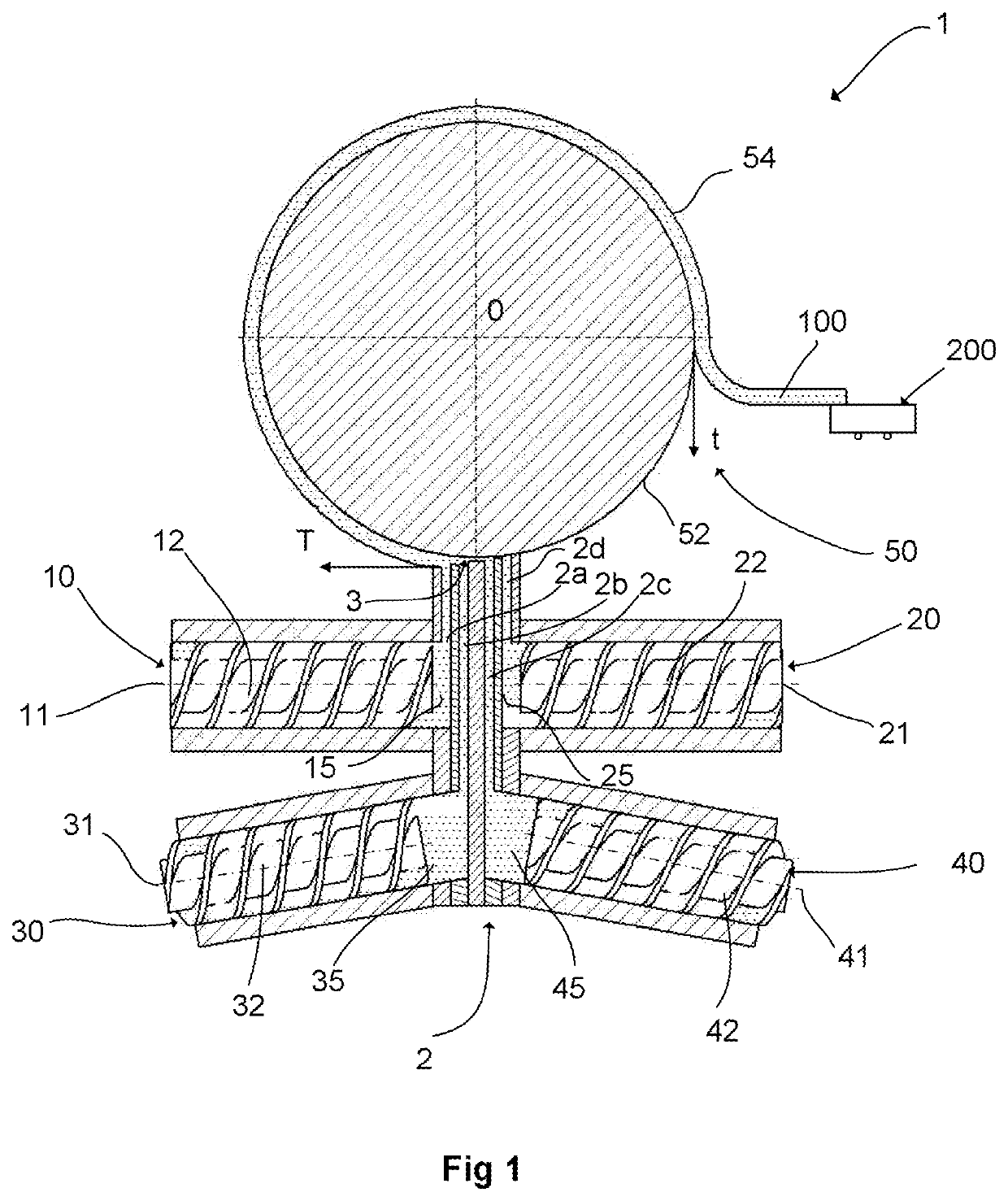
[0042]In the disclosure, as best shown on FIG. 2, the diameter of the roller 50 or the external diameter is equal to or greater than 0.6 m and preferably between 0.6 m and 4 m, and even more preferably between 1 and 2.5 m. During laboratory tests, it was found that a roller with a large diameter compared with rollers of extrusion machines of the prior art, which are generally between 200 and 500 mm, allows the coextruded profiled element strip to remain on the roller for longer while avoiding impressing thereon an excessively large radius of curvature.

[0043]Such a rigid roller with large diameter requires a robust structure of the support and rotational bearings, and good precision in the positioning of the roller. Preferably, the roller comprises a first cooling system for its external surface 52, for example in the form of a temperature-controlled water circuit, which allows cooling of the profiled element strip 100, and a second cooling system for its support bearings (not illust...

second embodiment

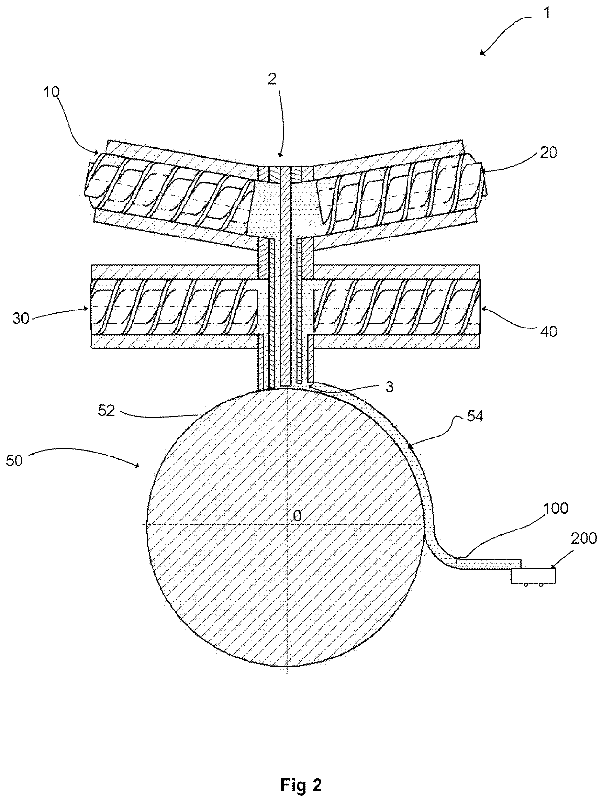
[0055]When using a roller of diameter equal to or greater than 1 m in the second embodiment, it was found that holding the coextruded product over an angular distance of between 180° and 210° of the external surface 52 of the roller gives very good results in terms of stress relaxation.

third embodiment

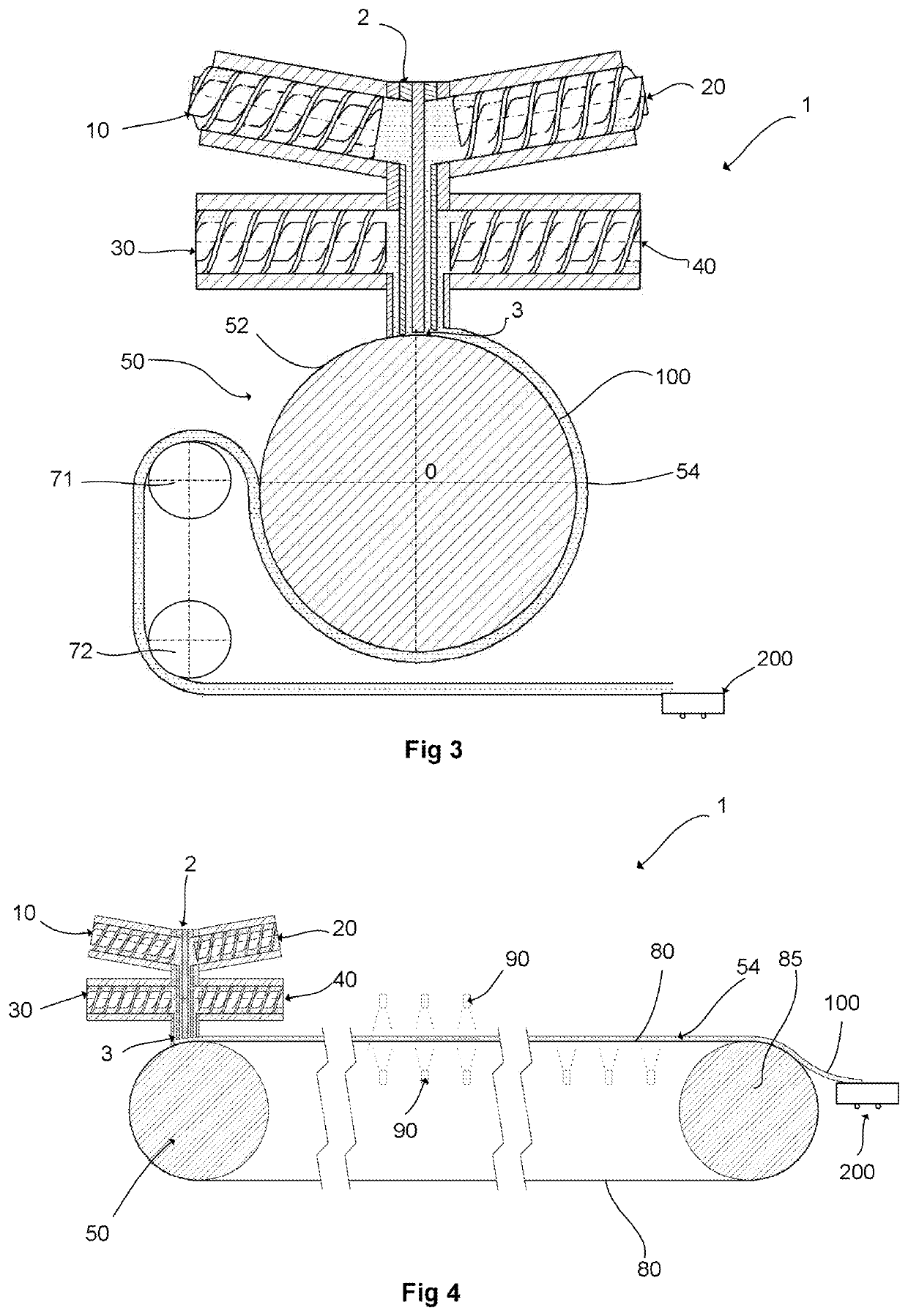
[0056]In a third embodiment and as shown more clearly in FIG. 4, the roller 50 drives an endless belt 80 interposed between the die 3 and said roller, such that the die 3 cooperates with the roller 50 for shaping the profiled element strip by means of said belt.

[0057]In order to solve problems of construction of a roller 50 of large diameter, it is advantageous to install a belt which allows the coextruded profiled element strip to remain in position for much longer, and thus maximize the stress relaxation. Such a belt 80 is installed between two rollers, a first drive roller formed by the roller 50 of the roller tip, and a second roller 85 mounted so as to rotate freely. In a variant embodiment, the rollers 50 and 85 have a diameter of around 300 mm.

[0058]In order to guarantee an optimal service life of the belt 80, it is preferably made of stainless steel.

[0059]Controlling the belt speed is essential for obtaining the desired geometry of the coextruded profiled element strip 100. ...


PUM

PropertyMeasurementUnit
lengthaaaaaaaaaa
diameteraaaaaaaaaa
angleaaaaaaaaaa

Abstract

The machine includes an extrusion head having flow ducts, the inlet orifices of which are connected to the outlets of at least two extruders for supplying extruded strips made of elastomeric compounds. The outlet orifices lead into a die which is adjacent to a roller and is designed to cooperate with the latter to shape the profiled element strip. The roller has a central axis surrounded by an external surface intended to receive the profiled element strip and a means for driving the roller in rotation about its central axis. The flow ducts are mutually parallel and are perpendicular to the circumferential direction of the roller, and the profiled element strip is joined to the receiving surface of the roller along an equivalent length of at least 700 mm.

Description

CROSS-REFERENCE TO RELATED APPLICATION[0001]This application claims priority to and the benefit of PCT Patent Application No. PCT / FR2019 / 052164 filed on 17 Sep. 2019, entitled “COEXTRUSION MACHINE FOR ELASTOMERIC COMPOUNDS, AND METHOD FOR MANUFACTURING A PROFILED ELEMENT STRIP,” and French Patent Application No. 1858522, filed on Sep. 20, 2018, entitled “COEXTRUSION MACHINE FOR ELASTOMERIC COMPOUNDS, AND METHOD FOR MANUFACTURING A PROFILED ELEMENT STRIP”.BACKGROUND1. Field[0002]The disclosure relates to the field of the production of strips of coextruded visco-elastic products such as elastomeric products intended for the manufacture of tires. More particularly, it relates to the manufacture of coextruded complex profiled elements based on elastomeric compounds and intended for the manufacture of a tire tread or side wall.2. Related Art[0003]In the known fashion, in the manufacture of complex profiles by extrusion of at least two products in strip form, based on elastomeric compound...

Claims


Application Information

Patent Timeline
Patent Type & Authority Applications(United States)
IPC IPC(8): B29C48/35B29C48/21B29C48/345B29C48/305B29C48/08B29C48/355B29C48/49B29C48/87B29C48/885B29C48/88B29D30/06
CPCB29C48/35B29C48/21B29C48/345B29C48/307B29C48/08B29K2007/00B29C48/49B29C48/87B29C48/885B29C48/914B29D30/06B29C48/355B29C48/07B29C48/142B29L2009/00B29L2030/00
Inventor OUGIER, CHRISTOPHEHINC, HENRIJAUNET, NICOLASLETOCART, AMAUD
Owner CO GENERATE DES ESTAB MICHELIN
Why Eureka
Try Eureka