
Resonant switching power converter

a power converter and resonance technology, applied in the direction of dc-dc conversion, power conversion systems, climate sustainability, etc., can solve the problems of high inrush current of the capacitors of such conventional power converters, and achieve the effects of reducing voltage stress, soft starting, and reducing unwanted inrush curren

Active Publication Date: 2022-01-27
RICHTEK TECH
View PDF2 Cites 0 Cited by
  • Summary
  • Abstract
  • Description
  • Claims
  • Application Information

AI Technical Summary

Benefits of technology

The present invention allows for pre-charging and hot-swapping without needing a separate hot-swapping switch and controller. This invention also allows for soft starting without needing an additional upstream voltage regulator, reduces unwanted inrush current, and reduces voltage stress. Additionally, it supports a parallel operation which is useful for a multiphase resonant switched-capacitor converter (RSCC).

Problems solved by technology

The capacitors of such conventional power converter will suffer high inrush current when the switches Q1-Q10 are switching.

Method used


Image

  • Resonant switching power converter
  • Resonant switching power converter
  • Resonant switching power converter

Examples


Embodiment Construction

[0038]The drawings as referred to throughout the description of the present invention are for illustration only, to show the interrelations between the circuits and the signal waveforms, but not drawn according to actual scale of circuit sizes and signal amplitudes and frequencies.

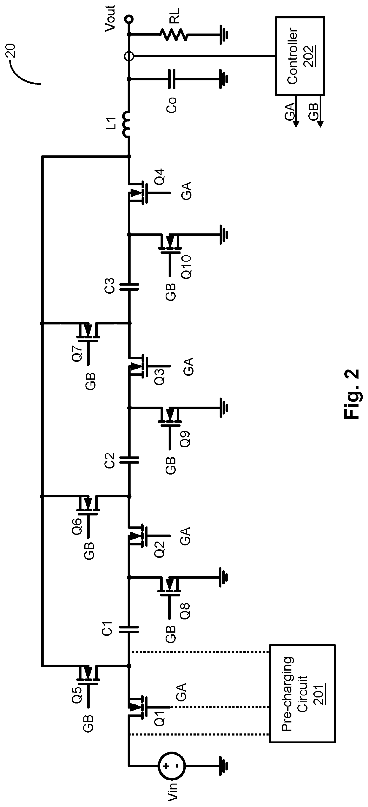
[0039]Please refer to FIG. 2, which shows a schematic circuit diagram of a resonant switching power converter according to an embodiment of the present invention. As shown in FIG. 2, the resonant switching power converter 20 of the present invention comprises: capacitors C1, C2 and C3, switches Q1, Q2, Q3, Q4, Q5, Q6, Q7, Q8, Q9 and Q10, an inductor L1, a pre-charging circuit 201 and a controller 202. The switches Q1, Q2 and Q3 are connected in series to the capacitors C1, C2 and C3, respectively. The switch Q4 is connected in series to the inductor L1. However, it should be understood that the implementation of the number of the capacitor of the resonant switching power converter 20 as three in the above-...


PUM


Abstract

A resonant switching power converter includes: capacitors, switches, at least one charging inductor, at least one discharging inductor and a pre-charging circuit. The pre-charging circuit controls a first switch of the switches when the resonant switching power converter operates in a pre-charging mode, to control an electrical connection relationship between the input voltage and a first capacitor of the capacitors and to control other capacitors of the capacitors, thus controlling the capacitors to be connected in parallel to one another or to be connected in series to one another, so that when a voltage drop across the first capacitor is lower than a predetermined voltage, the voltage drop across each capacitor is charged to the predetermined voltage. After operating in the pre-charging mode, the resonant switching power converter subsequently operates in a resonant voltage conversion mode, to thereby convert an input voltage to an output voltage.

Description

CROSS REFERENCE[0001]The present invention claims priority to U.S. 63 / 056,544 filed on Jul. 24, 2020 and claims priority to TW 109138686 filed on Nov. 5, 2020.BACKGROUND OF THE INVENTIONField of Invention[0002]The present invention relates to a resonant switching power converter; particularly, it relates to such resonant switching power converter capable of executing pre-charging operation.Description of Related Art[0003]Please refer to FIG. 1, which shows a schematic diagram of a conventional power converter. Under a charging operation, switches Q1, Q2, Q3 and Q4 are ON, whereas, switches Q5, Q6, Q7, Q8, Q9 and Q10 are OFF, so that a series connection of a capacitor C1, a capacitor C2 and a capacitor C3 is formed between an input voltage Vin and an output voltage Vout. On the other hand, under a discharging operation, switches Q5, Q6, Q7, Q8, Q9 and Q10 are ON, whereas, switches Q1, Q2, Q3 and Q4 are OFF, so that a parallel connection of the capacitor C1, the capacitor C2 and the c...

Claims


Application Information

Patent Timeline
IPC IPC(8): H02M3/07
CPCH02M3/07H02M1/36H02M1/32H02M3/01H02M1/0058Y02B70/10
Inventor LIU, KUO-CHIYANG, TA-YUNGPAI, CHUNG-LUNG
Owner RICHTEK TECH
Learn More