Power supply rail system
- Summary
- Abstract
- Description
- Claims
- Application Information
AI Technical Summary
Benefits of technology
Problems solved by technology
Method used
Image

Examples
first embodiment
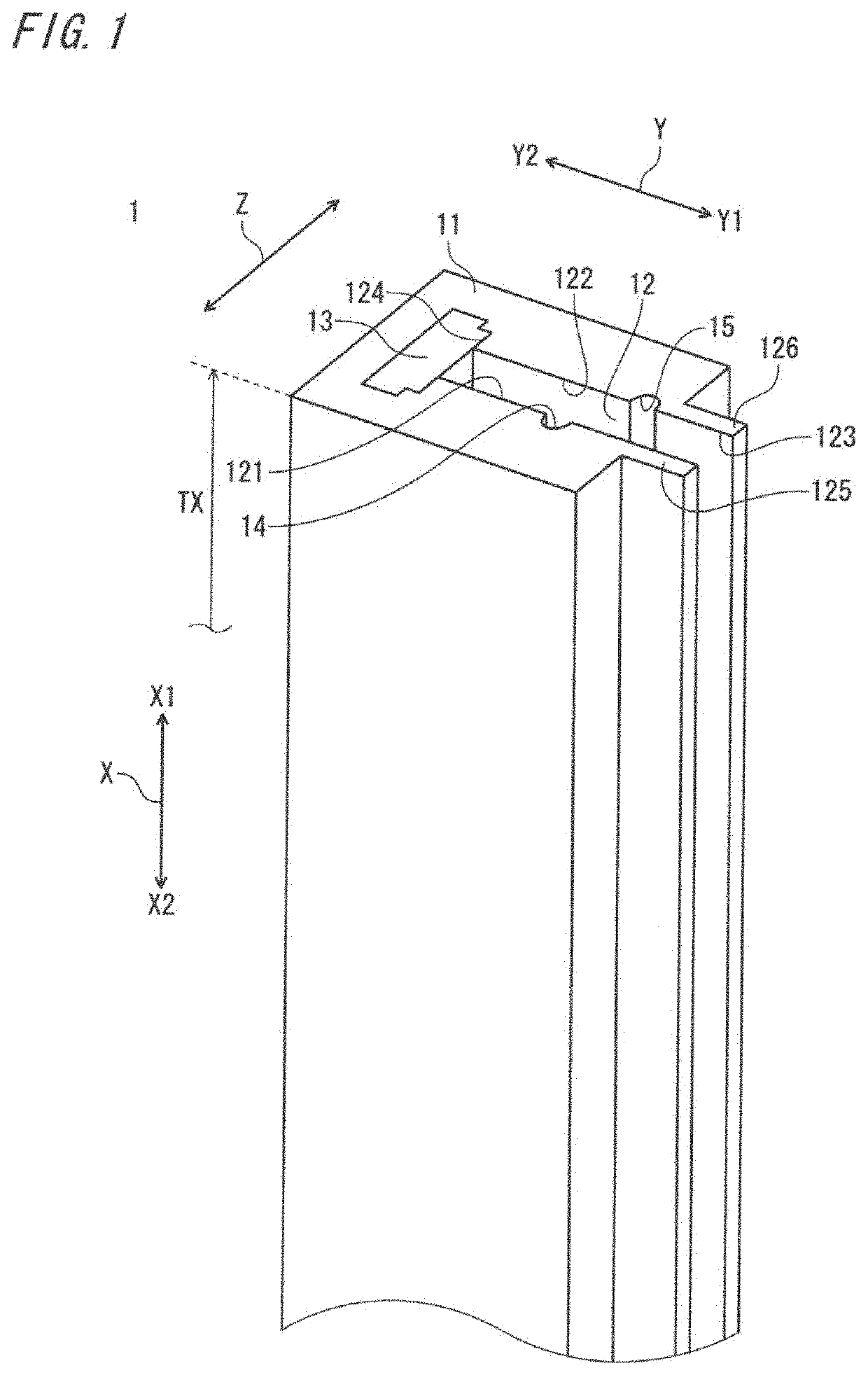
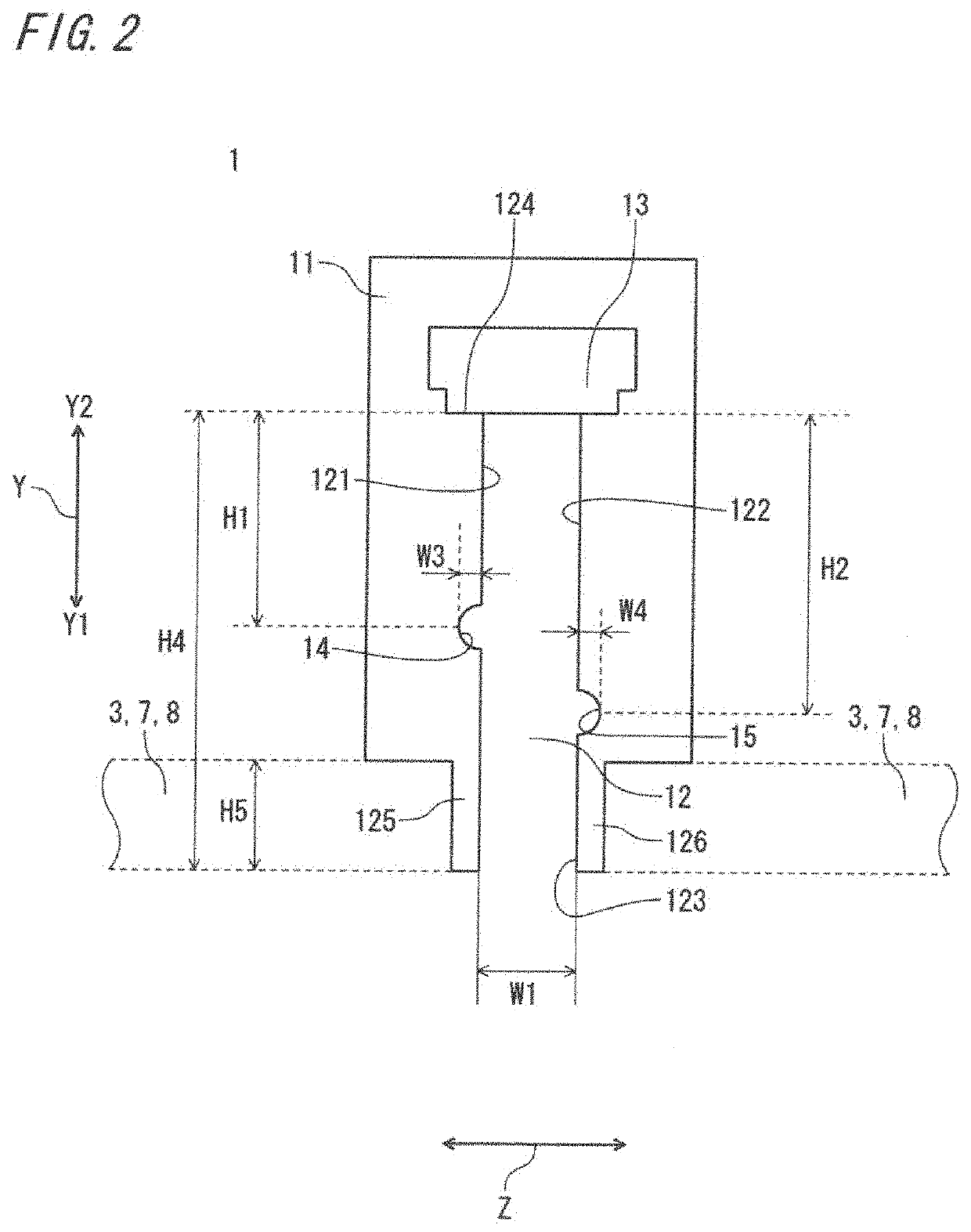
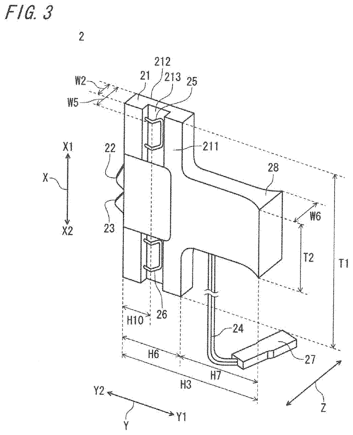
[0031]FIG. 1 is a perspective view showing a structure of a power supply rail of a power supply rail system according to the first embodiment of the present disclosure. FIG. 2 is a plan view showing a structure of the power supply rail shown in FIG. 1. FIG. 3 is a perspective view showing a structure of a power supply terminal of the power supply rail system according to the first embodiment. FIG. 4 is a perspective view of the power supply terminal shown in FIG. 3, as seen with a second direction reversed. FIG. 5 is a perspective view of the power supply terminal shown in FIG. 3, as seen with a first direction reversed. FIG. 6 is a schematic view showing a structure of a conductive portion in the power supply rail shown in FIG. 1.
[0032]FIG. 7 is a perspective view showing the case where the power supply terminal in the state shown in FIG. 3 is inserted into the power supply rail shown in FIG. 1. FIG. 8 is a perspective view showing the case where the power supply terminal in the st...
second embodiment
[0099]In the first embodiment, a simple structure example for the contact portion 27 of the power supply terminal 2 has been shown. However, without limitation thereto, other examples will be described with reference to FIG. 10 to FIG. 12. The structures other than the contact portion 27 are the same as in the first embodiment and therefore the description thereof is omitted as appropriate.
[0100]First, as shown in FIG. 10, the body portion 21 of the power supply terminal 2 is elongated toward the one-end side Y1 in the second direction Y, to form a contact portion 271 having a width in the third direction Z. The contact portion 271 also has a function as the hold portion 28.
[0101]Alternatively, as shown in FIG. 11, a part of the body portion 21 of the power supply terminal 2 on the one-end side Y1 in the second direction Y is bent in the third direction Z, to form a contact portion 272. Still alternatively, as shown in FIG. 12, a part of the body portion 21 of the power supply termi...
PUM
 Abstract
Description
Claims
Application Information
 - R&D Engineer
- R&D Manager
- IP Professional
- Industry Leading Data Capabilities
- Powerful AI technology
- Patent DNA Extraction
Browse by: Latest US Patents, China's latest patents, Technical Efficacy Thesaurus, Application Domain, Technology Topic.
© 2024 PatSnap. All rights reserved.Legal|Privacy policy|Modern Slavery Act Transparency Statement|Sitemap