Sensing properties of switching devices using back emf measurements

a switching device and back emf technology, applied in the field of switching devices, can solve the problems of torque oscillation and the switching device operating slightly differently

Active Publication Date: 2021-12-16
ROCKWELL AUTOMATION TECH
View PDF2 Cites 0 Cited by
  • Summary
  • Abstract
  • Description
  • Claims
  • Application Information

AI Technical Summary

Benefits of technology

The patent text describes a system that includes a switching device with a coil and an armature that moves between different positions to switch between different contacts. The system also includes a control system that monitors the voltage waveform of the coil during operation. The technical effects of this system may include improved control over the switching device and improved monitoring of its performance. A method is also described to receive the voltage waveform and determine its change over time, which can trigger a notification to a computing device. The patent also includes computer-goods that can be executed to perform these operational functions.

Problems solved by technology

As the switching devices open or close, electric power may be discharged as an electric arc and / or cause current oscillations to be supplied to the load, which may result in torque oscillations.
Over time, the switching devices begin to operate slightly differently due to contact wear and other conditions.

Method used


Image

  • Sensing properties of switching devices using back emf measurements
  • Sensing properties of switching devices using back emf measurements
  • Sensing properties of switching devices using back emf measurements

Examples


Embodiment Construction

[0020]One or more specific embodiments of the present disclosure will be described below. In an effort to provide a concise description of these embodiments, all features of an actual implementation may not be described in the specification. It should be appreciated that in the development of any such actual implementation, as in any engineering or design project, numerous implementation-specific decisions must be made to achieve the developers' specific goals, such as compliance with system-related and business-related constraints, which may vary from one implementation to another. Moreover, it should be appreciated that such a development effort might be complex and time consuming, but would nevertheless be a routine undertaking of design, fabrication, and manufacture for those of ordinary skill having the benefit of this disclosure.

[0021]When introducing elements of various embodiments of the present disclosure, the articles “a,”“an,”“the,” and “said” are intended to mean that th...


PUM


Abstract

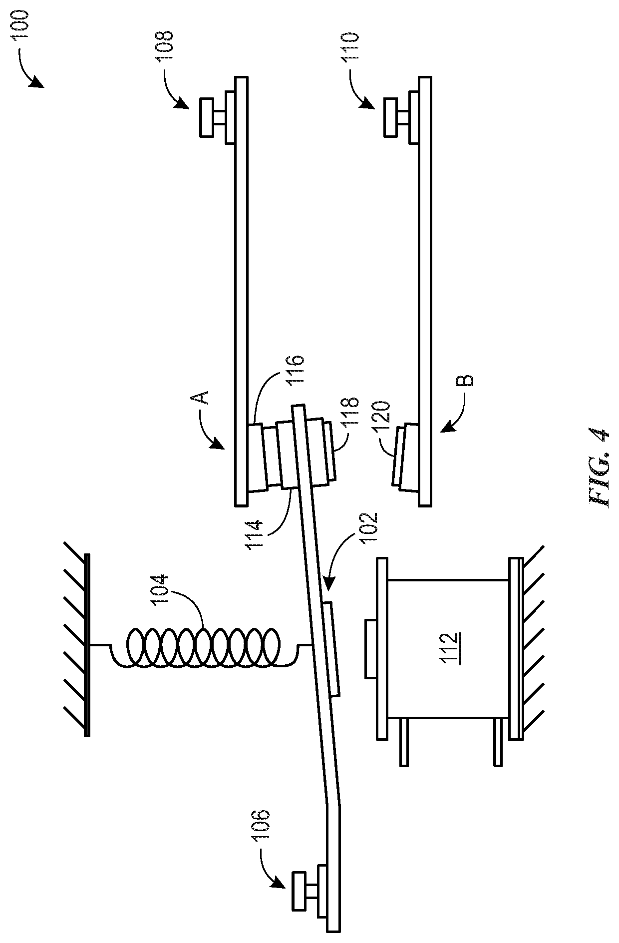
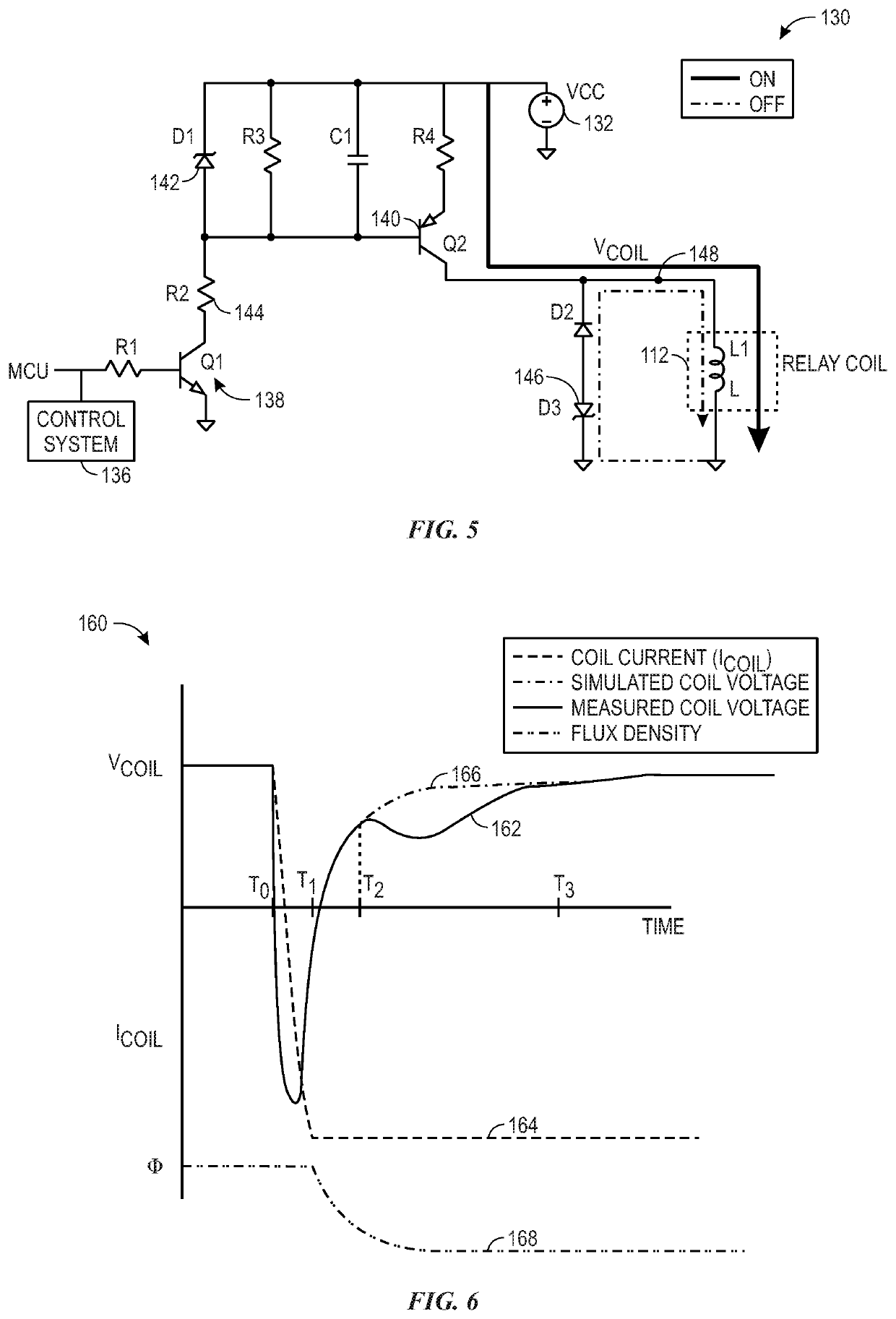
A system may include a switching device. The switching device may include an armature that may move between a first position that electrically couples the armature to a first contact and a second position that electrically couples the armature to a second contact. The switching device may also include a coil that may receive a voltage that magnetizes a core, thereby causing the armature to move from the first position to the second position. The system may also include a control system that may monitor a voltage waveform associated with the coil during an open operation of the switching device.

Description

BACKGROUND[0001]The present disclosure relates generally to switching devices, and more particularly to operation and configuration of the switching devices. Switching devices are generally used throughout industrial, commercial, material handling, process and manufacturing settings, to mention only a few. As used herein, “switching device” is generally intended to describe any electromechanical switching device, such as mechanical switching devices (e.g., a contactor, a relay, air break devices, and controlled atmosphere devices) or solid-state devices (e.g., a silicon-controlled rectifier (SCR)). More specifically, switching devices generally open to disconnect electric power from a load and close to connect electric power to the load. For example, switching devices may connect and disconnect three-phase electric power to an electric motor.[0002]As the switching devices open or close, electric power may be discharged as an electric arc and / or cause current oscillations to be suppl...

Claims


Application Information

Patent Timeline
Patent Type & Authority Applications(United States)
IPC IPC(8): H01H47/00
CPCH01H47/002
Inventor CARLSON, ANDREW E.ADKINS, KYLE B.
Owner ROCKWELL AUTOMATION TECH
Why Eureka
Try Eureka