Miniature step motor with independent phase stators

a step motor and phase stators technology, applied in the field of step motors, can solve the problems of insufficient torque of the rotor with a hybrid stator, the inability to meet the demand for higher torque by a standard, and the narrowness of the magnet pole strip, etc., to achieve the effect of higher speed and higher speed

Inactive Publication Date: 2021-12-09
LIN ENG INC
View PDF0 Cites 0 Cited by
  • Summary
  • Abstract
  • Description
  • Claims
  • Application Information

AI Technical Summary

Benefits of technology

[0012]The invention is preferably designed for a. 90° stepper. Using a permanent magnet rotor having one pole-pair of magnets—one North pole & one South pole—ensures that the magnets are wide enough to generate a usable magnetic flux in a small diameter (such as 3 or 4 mm) rotor.
[0013]To produce a usable torque, every miniature motor is accompanied by a small speed reducer (gearbox). The resolution of the stepper is no longer important. Instead, the higher speed become more important. The invention has 90° per full step motor to achieve higher speed than finer resolution (e.g. 18°) steppers with the same pulse rates.
[0014]The invention is aiming for an overall motor size that is smaller than 13 mm in diameter. The novel design can apply to miniature step motors with overall sizes from 10 mm to 4 mm. Corresponding rotor diameters are smaller than 6½ mm, and about 2 mm for the smallest step motors.

Problems solved by technology

The magnet pole strips become very narrow when the rotor's outer diameter (OD) is small and cannot produce enough magnetic flux to generate a significant torque.
Thus, the demand for higher torque cannot be fulfilled by a standard can-stack PM stepper.
Using a permanent magnet (PM) type rotor with a hybrid stator cannot produce enough torque in most cases due to limitations upon the rotor's magnetic pole width.
This narrow width cannot produce enough magnetic strength from the permanent magnet rotor.

Method used


Image

  • Miniature step motor with independent phase stators
  • Miniature step motor with independent phase stators
  • Miniature step motor with independent phase stators

Examples


Embodiment Construction

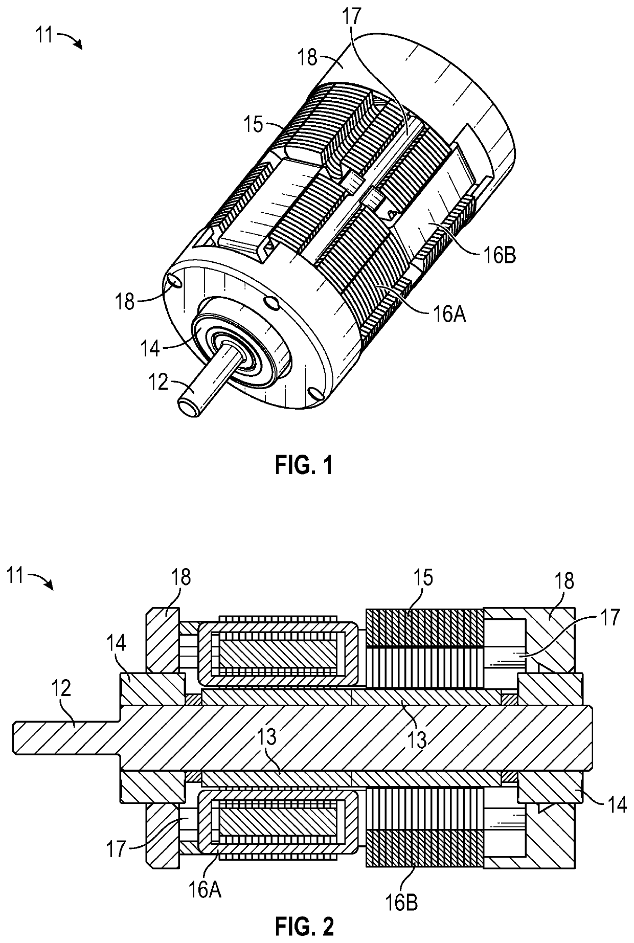
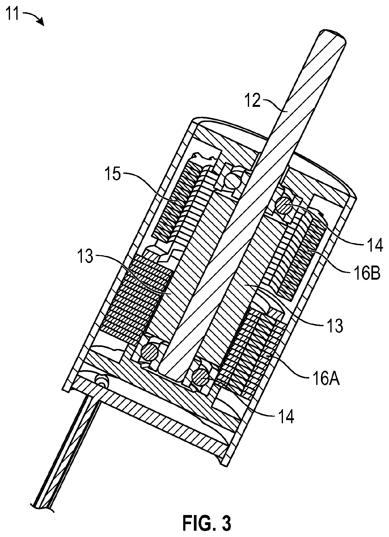
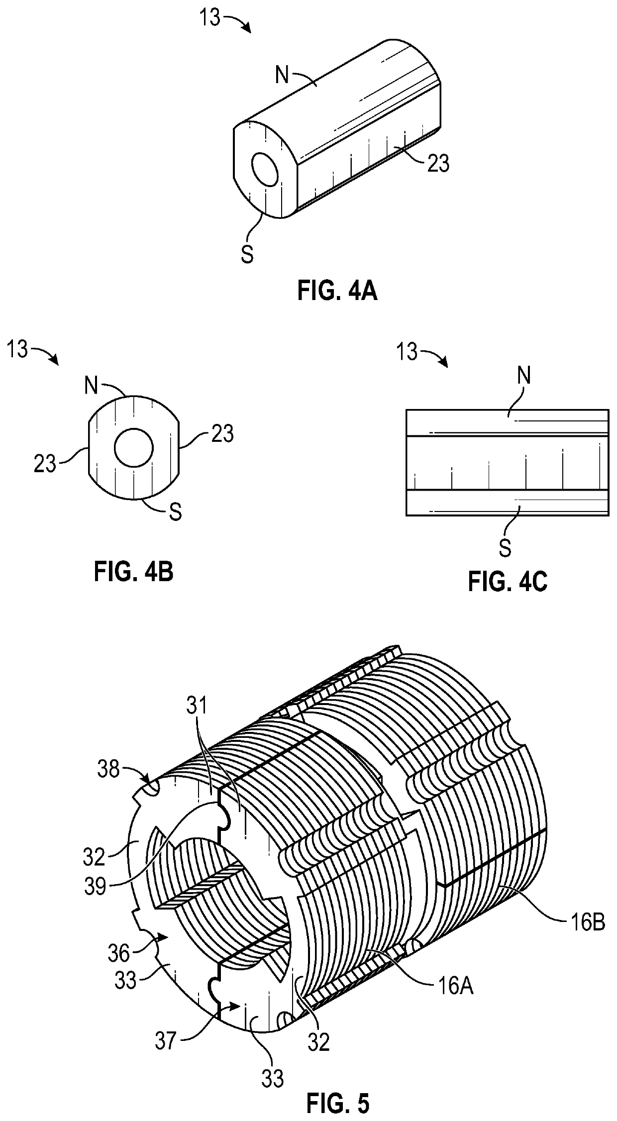
[0023]A primary goal is to make a miniature motor that is both easy to manufacture and has relatively higher torque than a conventional stepper design. To achieve this objective, the motor's stator has been separated into identical phase-stators, e.g. a pair of phase-stators A and B for a 2-phase stepper, each of which in turn are assembled from two identical individual sub-stators with windings. Rather than using a winding needle to wind around stator poles after the stator has been assembled, we provide coils that can be wound easily around the respective individual sub-stators prior to assembly. Since each coil generates its own independent magnetic flux path, no losses are created when the sub-stators are assembled. For example, the invention can apply to 2-phase bipolar motors having 4 uniform stator poles. The pair of phase-stators A and B are oriented relative to each other with a 90° axial rotational shift. (In an alternative embodiment, if corresponding stacked sections of ...


PUM


Abstract

A miniature step motor is constructed with a permanent magnet rotor and a hybrid stator assembly. The rotor, mounted for rotation on an axial shaft, has one or more rotor sections or pieces with a pair of magnetic poles on opposed circumferential surfaces of each piece. The stator assembly, with an inner diameter to receive the rotor, is formed from a stack of bipolar phase-stators positioned in different axial planes, each phase-stator interacting with a rotor section via a two-dimensional magnetic flux path that is independent of every other phase-stator in the stack. The at least one rotor section and the phase-stators have different amounts of rotor-stator rotational offsets at specified angles 180°/N relative to each other about the axial shaft, where N is the number of motor phases. The phase-stators can be mutually offset from one another, or the rotor sections can be mutually offset.

Description

CROSS-REFERENCE TO RELATED APPLICATION[0001]This application claims priority under 35 U.S.C. 119(e) from prior U.S. provisional application No. 63 / 033,997, filed Jun. 3, 2020.TECHNICAL FIELD[0002]This invention relates to step motors, that is, electric motor structures designed to rotate step-by-step between established electromagnetic detent positions and specially to step motors having permanent magnet (PM) type rotors and hybrid type stators. More particularly, the invention relates to step motors having design features that permit manufacture of ever smaller motors, with special attention to the demand for low noise, increased motor speeds, high / low speed control, and higher torque.BACKGROUND ART[0003]Demand for smaller motors is high for a number of applications, such as medical and laboratory equipment (e.g. centrifuges), as well as many positioning and speed control devices used in motion control (e.g. pumps, fans, printers and copiers, and even window drapery open / close cont...

Claims


Application Information

Patent Timeline
Patent Type & Authority Applications(United States)
IPC IPC(8): H02K19/10H02K37/14H02K15/06
CPCH02K19/10H02K15/02H02K15/062H02K37/14H02K2213/03H02K1/148H02K5/15H02K15/16
Inventor LIN, TED T.
Owner LIN ENG INC
Why Eureka
Try Eureka