
Image forming apparatus

a technology of forming apparatus and forming drum, which is applied in the direction of electrographic process apparatus, instruments, optics, etc., can solve the problem of insufficient removal of the substance adhesion to the surface of the photosensitive drum

Pending Publication Date: 2021-12-02
CANON KK
View PDF1 Cites 2 Cited by
  • Summary
  • Abstract
  • Description
  • Claims
  • Application Information

AI Technical Summary

Benefits of technology

This patent describes an image forming apparatus that can rotate to change the image being produced. The apparatus includes an image bearing member and an exposure portion that creates the first layer of the image. A developer carrying member supplies the material needed to develop the image on the image bearing member, and a controller controls the movement of the image bearing member and developer carrying member. After creating the image, the controller stops the movement of the developer carrying member and rotates the image bearing member, while ensuring that the amount of developer in the developing portion is smaller than it was during the image creating process. This results in reduced wear and tear on the image bearing member.

Problems solved by technology

Therefore, the toner acts as a lubricant such that rubbing between the developing roller and the photosensitive drum is reduced, and as a result, depending on the amount or strength of the adhered substance, such as toner or an external additive, adhered to the surface of the photosensitive drum, it may be impossible to sufficiently remove the substance adhered to the surface of the photosensitive drum.

Method used


Image

  • Image forming apparatus
  • Image forming apparatus
  • Image forming apparatus

Examples


first embodiment

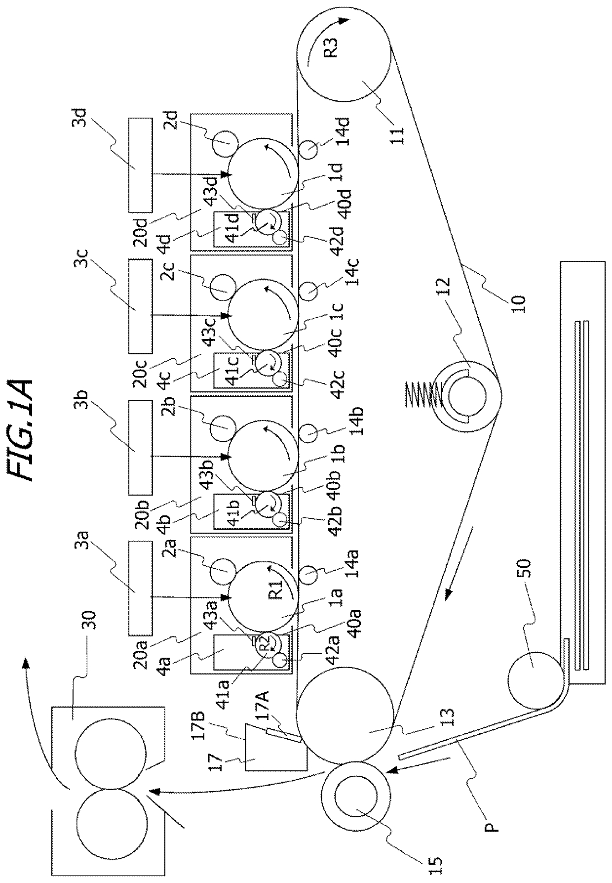
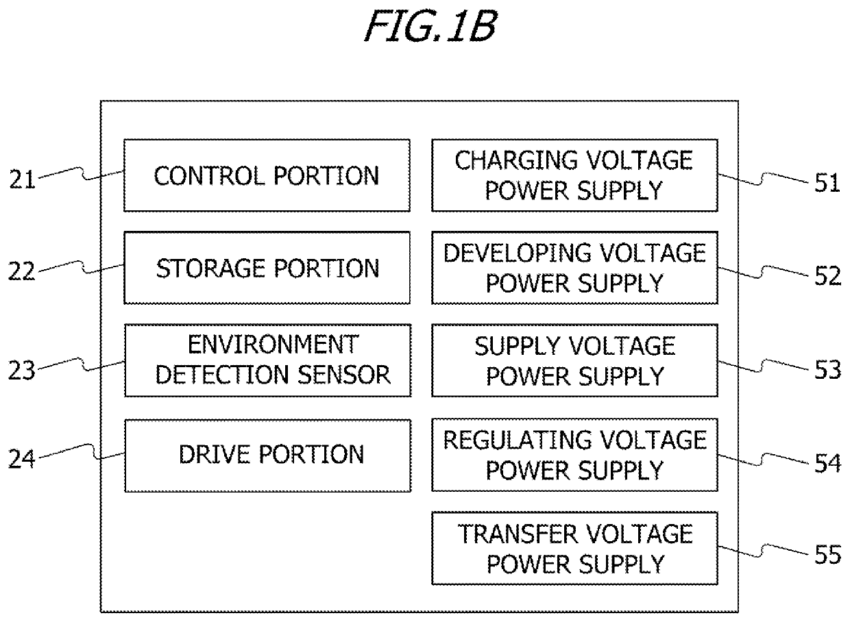
[0019]The present invention relates specifically to an image forming apparatus that uses a so-called drum cleanerless system not having means for cleaning the image bearing member. FIG. 1A is a schematic view showing an example of a color image forming apparatus. The configuration and operation of the image forming apparatus according to this embodiment will be described using FIG. 1A. Note that the image forming apparatus of this embodiment is a so-called tandem-type printer provided with image forming stations 20a to 20d serving as image forming portions. A first image forming station 20a forms a yellow (Y) image, while a second image forming station 20b forms a magenta (M) image. A third image forming station 20c forms a cyan (C) image, while a fourth image forming station 20d forms a black (Bk) image. Apart from the color of the toner housed therein, the image forming stations 20a to 20d are configured identically, and the first image forming station 20a will be used in the foll...

second embodiment

[0058]In an image forming apparatus according to this embodiment, the control portion 21 records a number of printed images (the number of the image forming operations) following implementation of the preceding cleaning operation for removing substances adhered to the photosensitive drum 1 in the storage portion 22. Further, in the image forming apparatus according to this embodiment, the image forming operation is temporarily halted at the point where the recorded number of printed images reaches a predetermined threshold, whereupon the cleaning operation is implemented to remove substances adhered to the photosensitive drum 1. The control portion 21 controls driving of the photosensitive drum 1 and the developing roller 41 so that every time the number of printed images following implementation of the preceding cleaning operation reaches the predetermined threshold, the next cleaning operation is implemented. The threshold for the number of printed images from implementation of th...

third embodiment

[0067]An image forming apparatus of this embodiment is installed with the environment detection sensor 23 for detecting the temperature and the humidity on the periphery of the image forming apparatus, and the implementation time of the cleaning operation is modified in accordance with detection results acquired by the environment detection sensor 23. The environment detection sensor 23, serving as an acquisition portion, acquires environment information (environment information of the image forming apparatus) including the temperature and / or the humidity on the periphery of the image forming apparatus. The control portion21 determines the implementation time (execution time) of the cleaning operation in accordance with the environment information of the image forming apparatus.

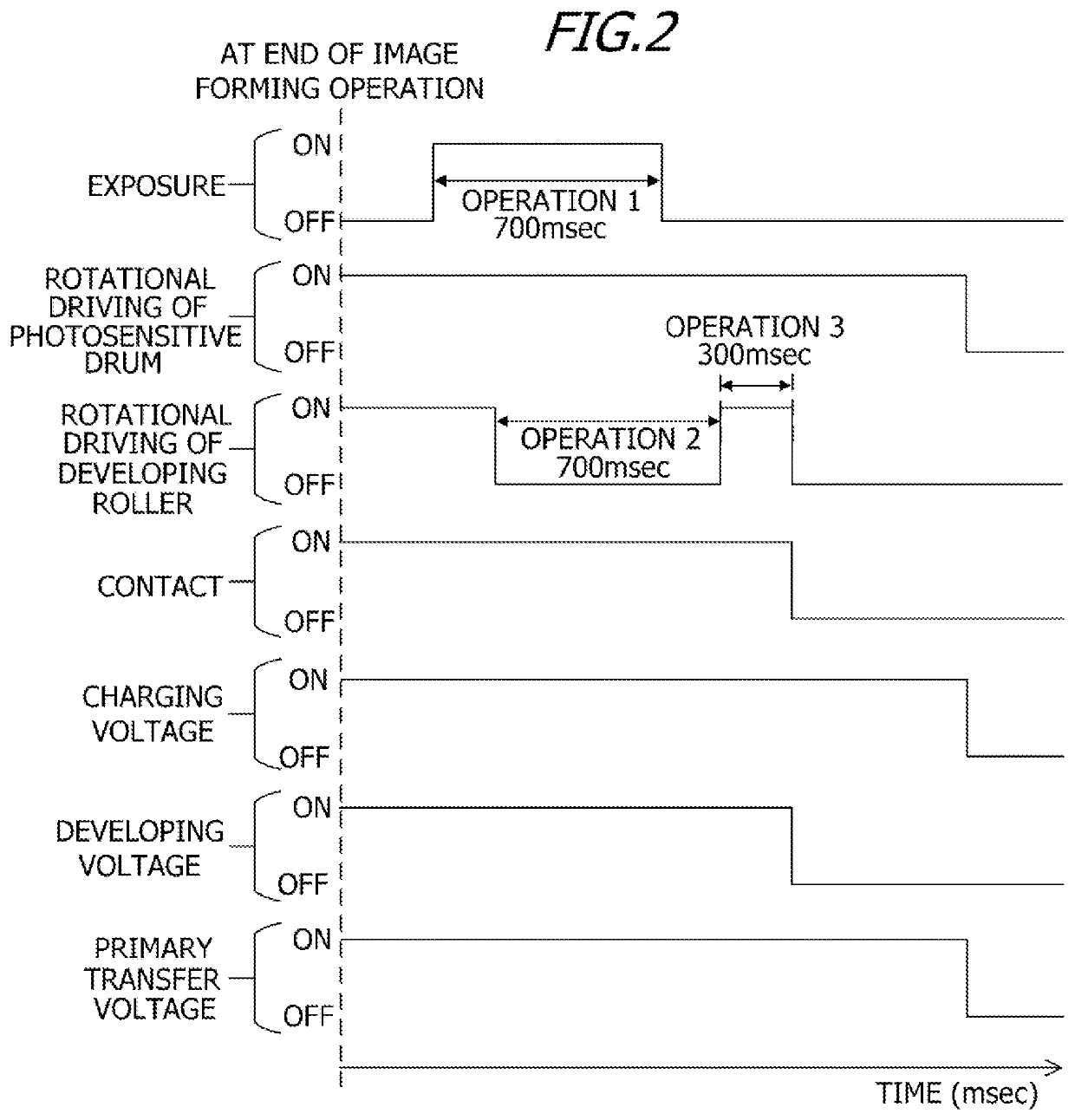
[0068]FIG. 6 is a timing chart of the cleaning operation performed by the image forming apparatus of this embodiment. The parameters of FIG. 6 are similar to those of FIG. 2. In this embodiment, the implement...


PUM


Abstract

An image forming apparatus forms an image on a recording medium and includes a rotatable image bearing member, and a rotatable developer carrying member that carries a developer, forms a developing portion by contacting the image bearing member, and forms a developer image on a surface of the image bearing member by supplying the developer to an electrostatic latent image formed on the surface of the image bearing member in the developing portion. After performing an image forming operation, a controller controls driving of the image bearing member and the developer carrying member to perform a rotation operation for rotating the image bearing member with rotation of the developer carrying member stopped in a state where an amount of carried developer in the developing portion during the rotation operation is smaller than the amount of carried developer in the developing portion during the image forming operation.

Description

BACKGROUND OF THE INVENTIONField of the Invention[0001]The present invention relates to an image forming apparatus that uses an electrophotographic process or the like.Description of the Related Art[0002]An image forming apparatus that forms images using an electrophotographic process, such as a copier or a laser printer, is available in the prior art. As a transfer process, the image forming apparatus transfers a toner image formed on a surface of a photosensitive drum serving as an image bearing member onto an intermediate transfer member or a recording material through electrostatic transfer by applying a voltage from a voltage supply to a transfer member disposed in a part opposing the photosensitive drum. When toner images are formed in a plurality of colors, the toner images in the plurality of colors are formed on the surface of the intermediate transfer member or the recording material by repeatedly executing this transfer process with respect to the toner images of the plur...

Claims


Application Information

Patent Timeline
Patent Type & Authority Applications(United States)
IPC IPC(8): G03G15/06G03G15/08
CPCG03G15/065G03G15/0812
Inventor TETSUNO, SHUICHI
Owner CANON KK
Learn More