
Device for determining a parasitic resistance in video endoscopes

Pending Publication Date: 2021-11-25
OLYMPUS WINTER & IBE
View PDF0 Cites 0 Cited by
  • Summary
  • Abstract
  • Description
  • Claims
  • Application Information

AI Technical Summary

Benefits of technology

The invention is about a device that can measure the resistance of an electronic circuit used in a video endoscope. The device is designed to be reliable and cost-effective, meaning it can be made with only a few or no extra components. The technical effect of this invention is to provide a better way to measure the resistance of an electronic circuit, which can help improve the performance and reliability of video endoscopes.

Problems solved by technology

During autoclaving of video endoscopes, it is possible, for example, for moisture to enter the handle and thus cause problems with parasitic resistances.

Method used


Image

  • Device for determining a parasitic resistance in video endoscopes
  • Device for determining a parasitic resistance in video endoscopes

Examples


Embodiment Construction

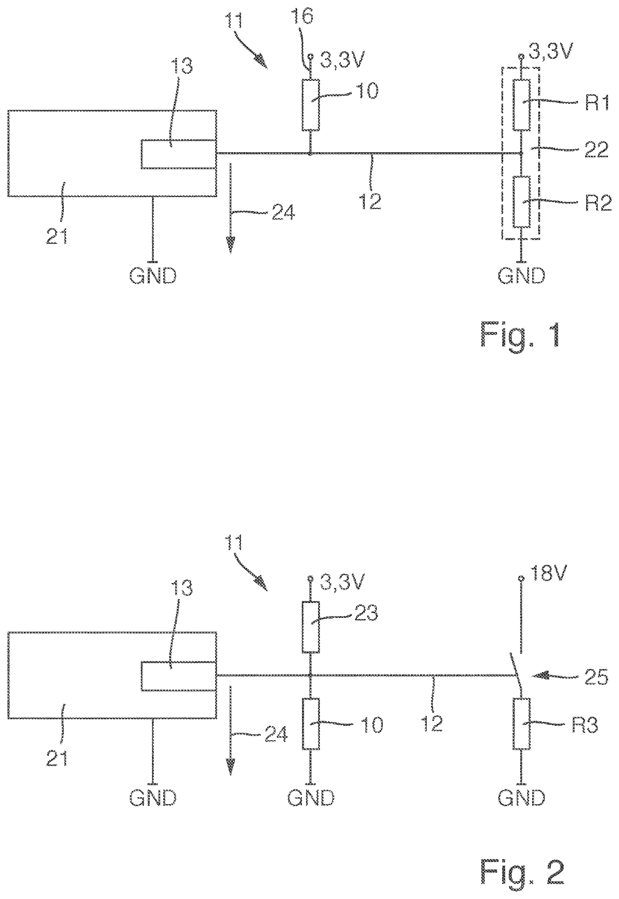
[0034]FIG. 1 schematically shows a circuit diagram of a device for determining a parasitic resistance 10 of an electronic circuit 11 for a video endoscope. A microcontroller 21 having an analog-digital converter 13, or AD converter, is provided. The input of the AD converter 13 is connected to a potential-determining conductor 12, to which a potential that corresponds to a voltage 24 to be measured is applied. The potential-determining conductor 12 is connected to a voltage divider 22, which comprises two resistors R1, R2. The potential-determining conductor 12 is connected to the voltage divider 22 between these two resistors R1, R2. A reference potential conductor 16 having a potential of, by way of example, 3.3 volts is provided. The voltage divider 22 has 3.3 volts on one side and is connected to ground GND on the other side.

[0035]In the presence of a parasitic resistance 10 between the potential-determining conductor 12 and the reference potential conductor 16, the voltage 24 t...


PUM


Abstract

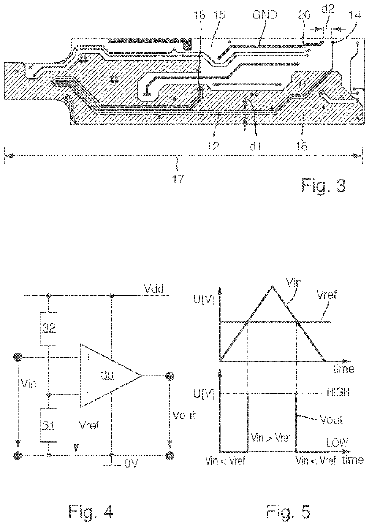
A device for determining a parasitic resistance of an electronic circuit for a video endoscope, the device including: a potential determining device; a printed circuit board; and a potential-determining conductor which is connected to the potential-determining device, the potential-determining conductor being situated on the printed circuit board. Wherein the potential-determining conductor is arranged along a path on the printed circuit board next to a reference potential conductor, and the potential-determining device is configured to determine a parasitic resistance between the potential-determining conductor and the reference potential conductor.

Description

CROSS-REFERENCE TO RELATED APPLICATION[0001]The present application is a continuation of PCT / EP2020 / 052570 filed on Feb. 3, 2020, which is based upon and claims the benefit to DE 10 2019 103 287.3 filed on Feb. 11, 2019, the entire contents of each of which are incorporated herein by reference.BACKGROUNDField[0002]The present disclosure relates to video endoscopes and more particularly to a device for determining a parasitic resistance of an electronic circuit for a video endoscope, comprising a potential-determining conductor which is connected to a potential-determining device, wherein the potential-determining conductor is situated on a printed circuit board.Prior Art[0003]The functioning of electronic circuits in video endoscopes can be influenced by parasitic resistances. A parasitic resistance is an unreliable resistance between two independent signals or levels or conductors of an electronic circuit. There are electronic circuits that are sensitive to faults of this kind, for...

Claims


Application Information

Patent Timeline
IPC IPC(8): H04N17/00
CPCH04N17/00G01R31/58G01R27/02G01R19/165G01R31/52G01R31/2825
Inventor PABST, SVENJUNGBAUER, SEBASTIAN
Owner OLYMPUS WINTER & IBE
Learn More