
Projection Method of Projection System for Use to Correct Image Distortion on Uneven Surface

a projection system and image distortion technology, applied in the field of image processing, can solve the problems of image distortion on the projection surface, and the method cannot overcome the problem of image distortion

Inactive Publication Date: 2021-11-25
WELTREND SEMICON INC
View PDF2 Cites 7 Cited by
  • Summary
  • Abstract
  • Description
  • Claims
  • Application Information

AI Technical Summary

Benefits of technology

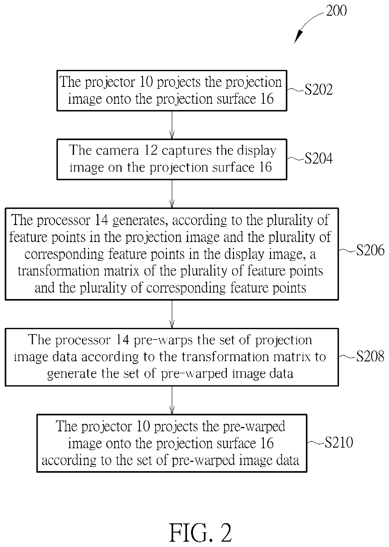
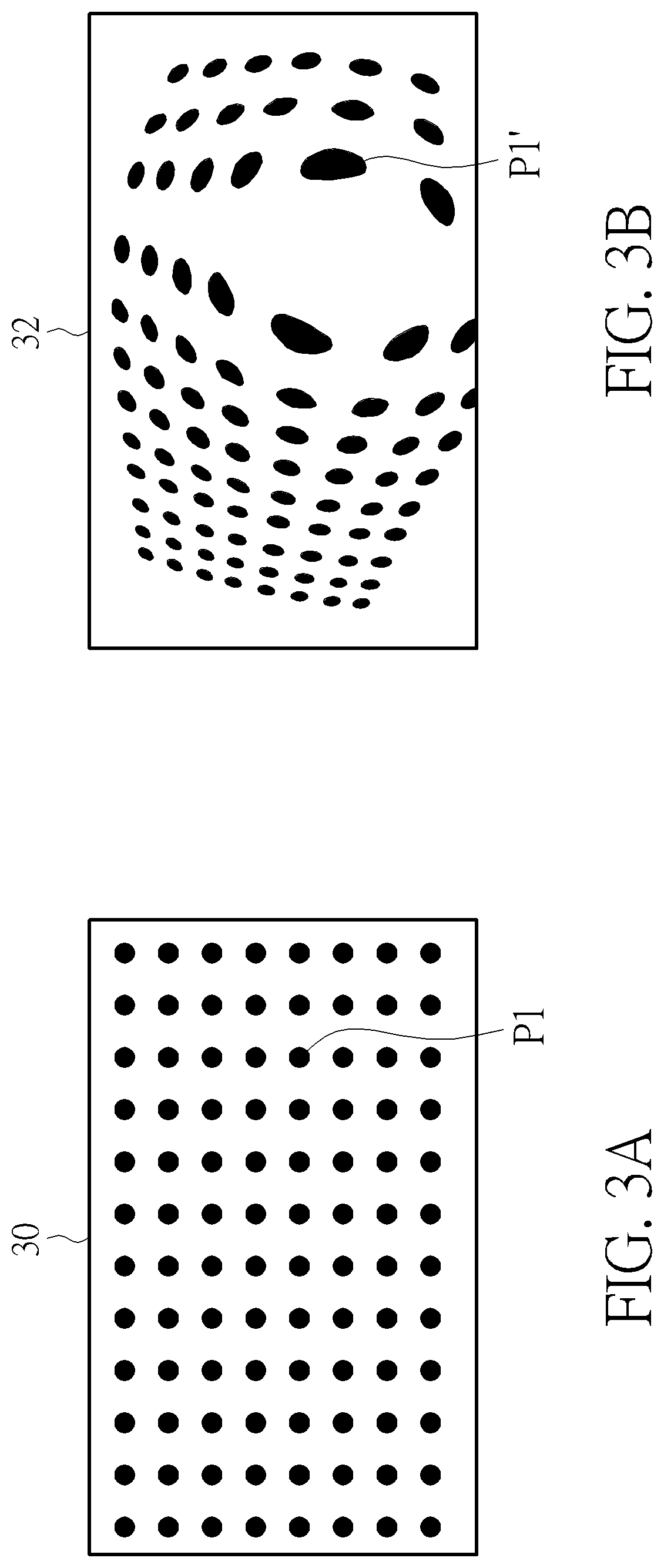
The invention provides a method for projecting an image onto a surface using a projector and a camera, which are separate components. The method includes using feature points in the image and the corresponding feature points in the camera to create a transformation matrix, pre-warping the image data based on the transformation matrix, and projecting the transformed image onto the surface. Additionally, the invention includes using a depth sensor and an inertia measurement unit to calibrate the projector and create a calibrated projection region for the image. This allows for more accurate and precise projection of the image onto the surface.

Problems solved by technology

In practice, images on the projection surface may be distorted owing to the projector being tilted or the projector projecting onto an uneven or inclined surface.
When the projection surface is uneven or curved, the traditional method cannot overcome the problem of image distortion.

Method used


Image

  • Projection Method of Projection System for Use to Correct Image Distortion on Uneven Surface
  • Projection Method of Projection System for Use to Correct Image Distortion on Uneven Surface
  • Projection Method of Projection System for Use to Correct Image Distortion on Uneven Surface

Examples


Embodiment Construction

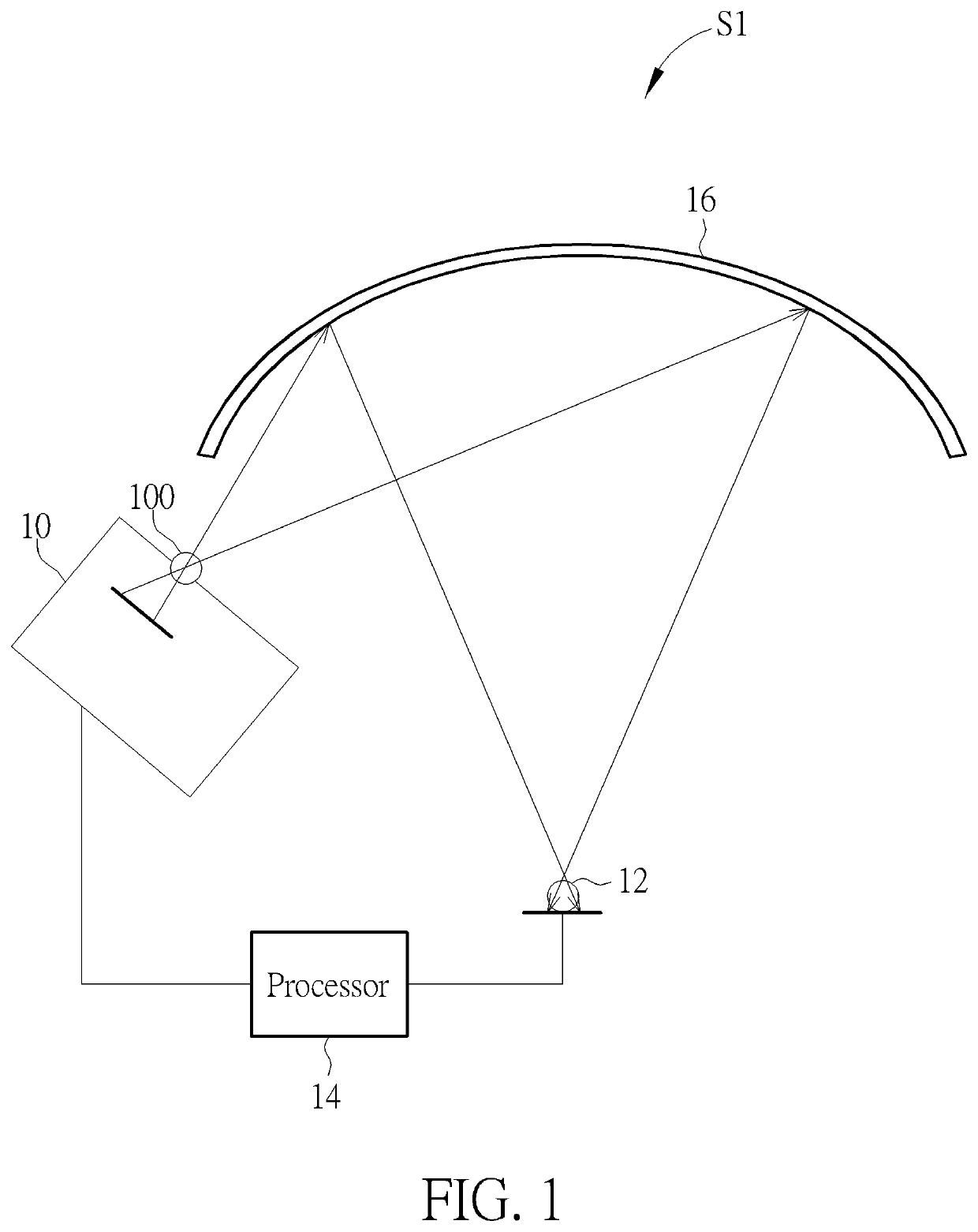
[0021]FIG. 1 is a schematic diagram of a projection system S1 according to an embodiment of the invention. The projection system S1 may include a projector 10, a camera 12 and a processor 14. The projector 10 may include a digital light processing device 100. The projector 10 and the camera 12 may be disposed separately, and both may be coupled to the processor 14. The processor 14 may be disposed in the projector 10, the camera 12, a computer, a mobile phone or a game console. The projector 10 may project onto the projection surface 16 via the digital light processing device 100 at an angle. The camera 12 may be disposed on a wall or at other fixtures directly opposite to the projection surface 16 or from the viewer's location. The projection surface 16 may be a flat surface, a curved surface, a corner, a ceiling, a spherical surface or other uneven surfaces. The horizontal viewing angle of the projector 10 may be substantially equal to 40 degrees, the vertical viewing angle of the...


PUM


Abstract

A projection system includes a projector, a depth sensor, an inertia measurement unit and a processor. The depth sensor and the inertia measurement unit are fixed at the projector. A projection method includes the inertia measurement unit performing a 3-axis acceleration measurement to generate an orientation of the projector, the depth sensor detecting a plurality of coordinates of a plurality of points on a projection surface, the processor performing a keystone correction according to at least the plurality of coordinates of the plurality of points on the projection surface to generate a calibrated projection region, the processor generating a set of data according to at least the orientation of the projector, the calibrated projection region and the plurality of coordinates, and the projector projecting a pre-warped image onto the projection surface according to the set of data.

Description

CROSS REFERENCE TO RELATED APPLICATION[0001]This non-provisional application claims priority of Taiwan patent application No. 109116519, filed on 19th May, 2020, included herein by reference in its entirety.BACKGROUND OF THE INVENTION1. Field of the Invention[0002]The invention relates to image processing, and specifically, to projection methods of a projection system.2. Description of the Prior Art[0003]A projector is an optical device that projects an image onto a projection surface. In practice, images on the projection surface may be distorted owing to the projector being tilted or the projector projecting onto an uneven or inclined surface. Conventionally, the projector may adopt a keystone correction by way of manual positioning and observation to achieve the optimal viewing projection correction. When the projection surface is uneven or curved, the traditional method cannot overcome the problem of image distortion. If the projection screen is too large and several projectors ...

Claims


Application Information

Patent Timeline
IPC IPC(8): G03B21/14
CPCG03B21/147H04N9/31H04N9/3179G03B21/2066
Inventor HSIEN, TAKAOTSAI, MENG-CHE
Owner WELTREND SEMICON INC
Learn More