
Digital slope analog to digital converter device and signal conversion method

a digital converter and digital slope technology, applied in the field can solve the problems of insufficient circuit architecture of analog to digital converters to meet the requirements of high performance and low power consumption

Active Publication Date: 2021-10-21
REALTEK SEMICON CORP
View PDF0 Cites 1 Cited by
  • Summary
  • Abstract
  • Description
  • Claims
  • Application Information

AI Technical Summary

Benefits of technology

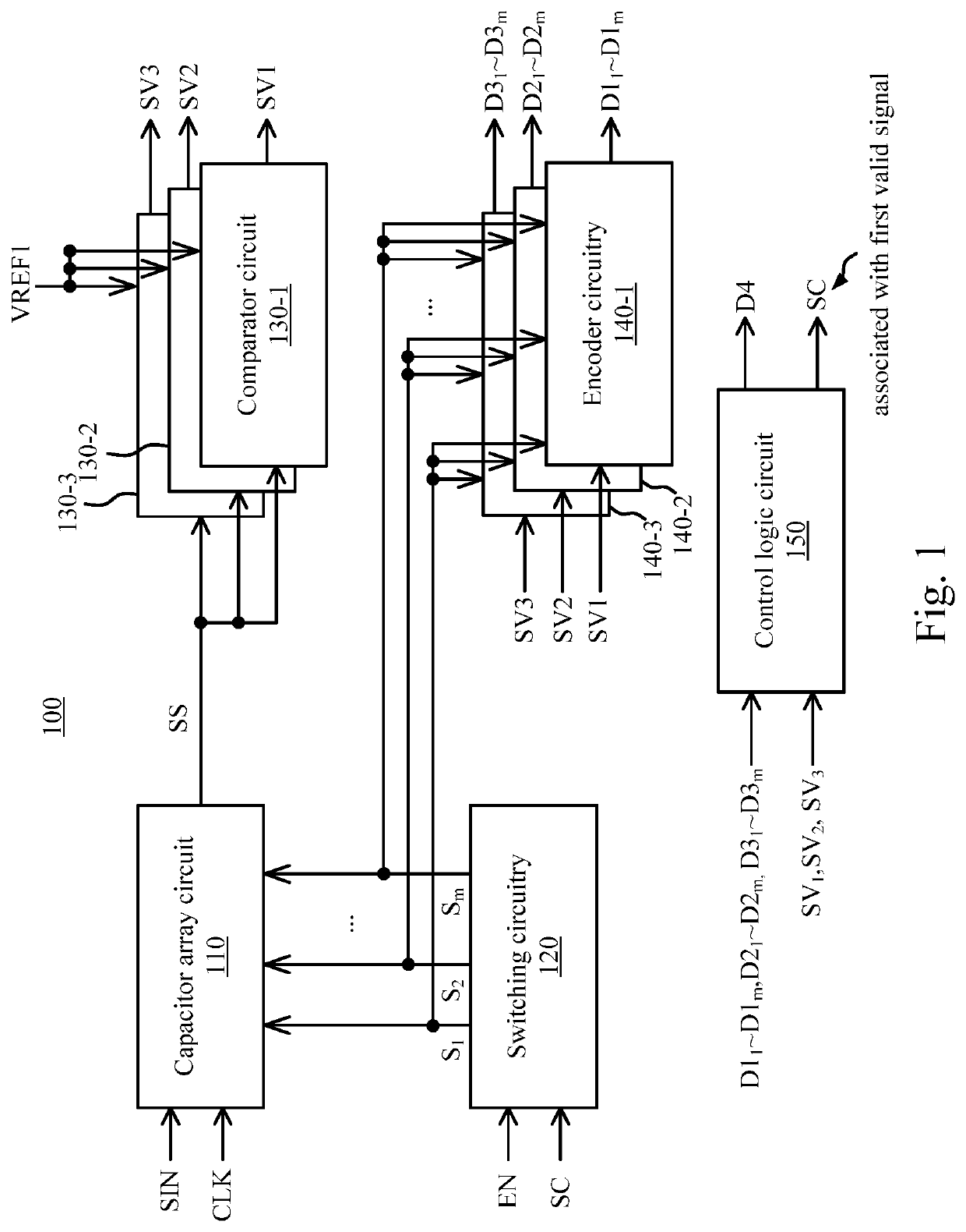
The present patent describes a device and method for converting signals. The device includes a capacitor array circuit, a switching circuitry, comparator circuits, encoder circuitries, and a control logic circuit. The method involves generating a first signal based on an input signal and switching signals, comparing the first signal with a predetermined voltage to generate a set of valid signals, generating a second digital code based on the valid signals, and performing a statistics calculation on the valid codes to generate a second digital code. The technical effects of the patent are to provide a device and method for accurate and efficient signal conversion without the need for complex and expensive equipment.

Problems solved by technology

However, the present circuit architecture of the analog to digital converter is insufficient to meet restrict requirements of high performance and low power consumption.

Method used


Image

  • Digital slope analog to digital converter device and signal conversion method
  • Digital slope analog to digital converter device and signal conversion method
  • Digital slope analog to digital converter device and signal conversion method

Examples


Embodiment Construction

[0011]The terms used in this specification generally have their ordinary meanings in the art and in the specific context where each term is used. The use of examples in this specification, including examples of any terms discussed herein, is illustrative only, and in no way limits the scope and meaning of the disclosure or of any exemplified term. Likewise, the present disclosure is not limited to various embodiments given in this specification.

[0012]In this document, the term “coupled” may also be termed as “electrically coupled,” and the term “connected” may be termed as “electrically connected.”“Coupled” and “connected” may mean “directly coupled” and “directly connected” respectively, or “indirectly coupled” and “indirectly connected” respectively. “Coupled” and “connected” may also be used to indicate that two or more elements cooperate or interact with each other. In this document, the term “circuitry” may be a system formed with at least one circuit, and the term “circuit” ma...


PUM


Abstract

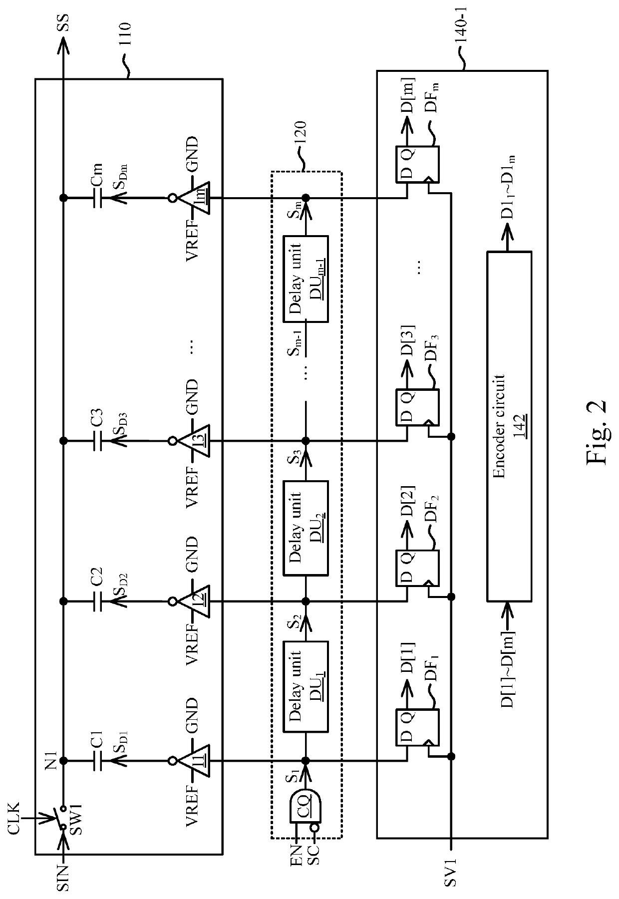
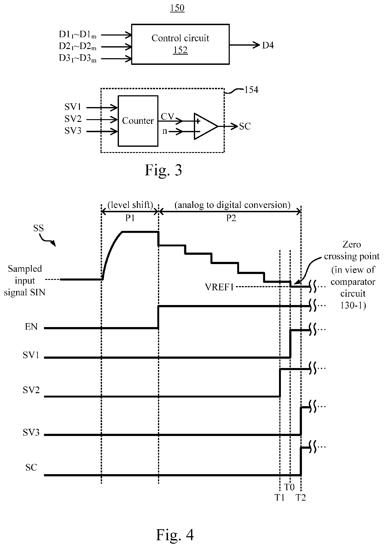
A digital slope analog to digital converter device includes a capacitor array circuit, a switching circuitry, comparator circuits, encoder circuitries, and a control logic circuit. The capacitor array circuit generates a first signal according to an input signal and switching signals. The switching circuitry generates the switching signals according to an enable signal and a first valid signal in the valid signals. Each of the comparator circuits compares the first signal with a predetermined voltage, in order to generate a corresponding one of the valid signals. Each of the encoder circuitries receives the switching signals according to a corresponding one of the valid signals, in order to generate a corresponding one of sets of first digital codes. The control logic circuit performs a statistics calculation according to the sets of first digital codes, in order to generate a second digital code.

Description

BACKGROUND OF THE INVENTION1. Field of the Invention[0001]The present disclosure relates to an analog to digital converter. More particularly, the present disclosure relates to an analog to digital converter that utilizes multiple comparators and a signal conversion method thereof.2. Description of Related Art[0002]An analog to digital converter has been widely utilized in various electronic devices, in order to generate a digital signal for subsequent signal processing. In practical applications, there is trade-off between a performance (e.g., resolution, low noise, bandwidth, etc.) of the analog to digital converter and power consumption. However, the present circuit architecture of the analog to digital converter is insufficient to meet restrict requirements of high performance and low power consumption.SUMMARY OF THE INVENTION[0003]In some embodiments, a digital slope analog to digital converter device includes a capacitor array circuit, a switching circuitry, a plurality of com...

Claims


Application Information

Patent Timeline
IPC IPC(8): H03M1/34
CPCH03M1/34H03M1/54H03M1/04H03M1/121H03M1/0678
Inventor HUANG, SHIH-HSIUNG
Owner REALTEK SEMICON CORP
Learn More