Air cushioning material
a technology of air cushioning and material, applied in the field of air cushioning material, to achieve the effect of not easily shifting or falling after packaging
- Summary
- Abstract
- Description
- Claims
- Application Information
AI Technical Summary
Benefits of technology
Problems solved by technology
Method used
Image
Examples
first embodiment
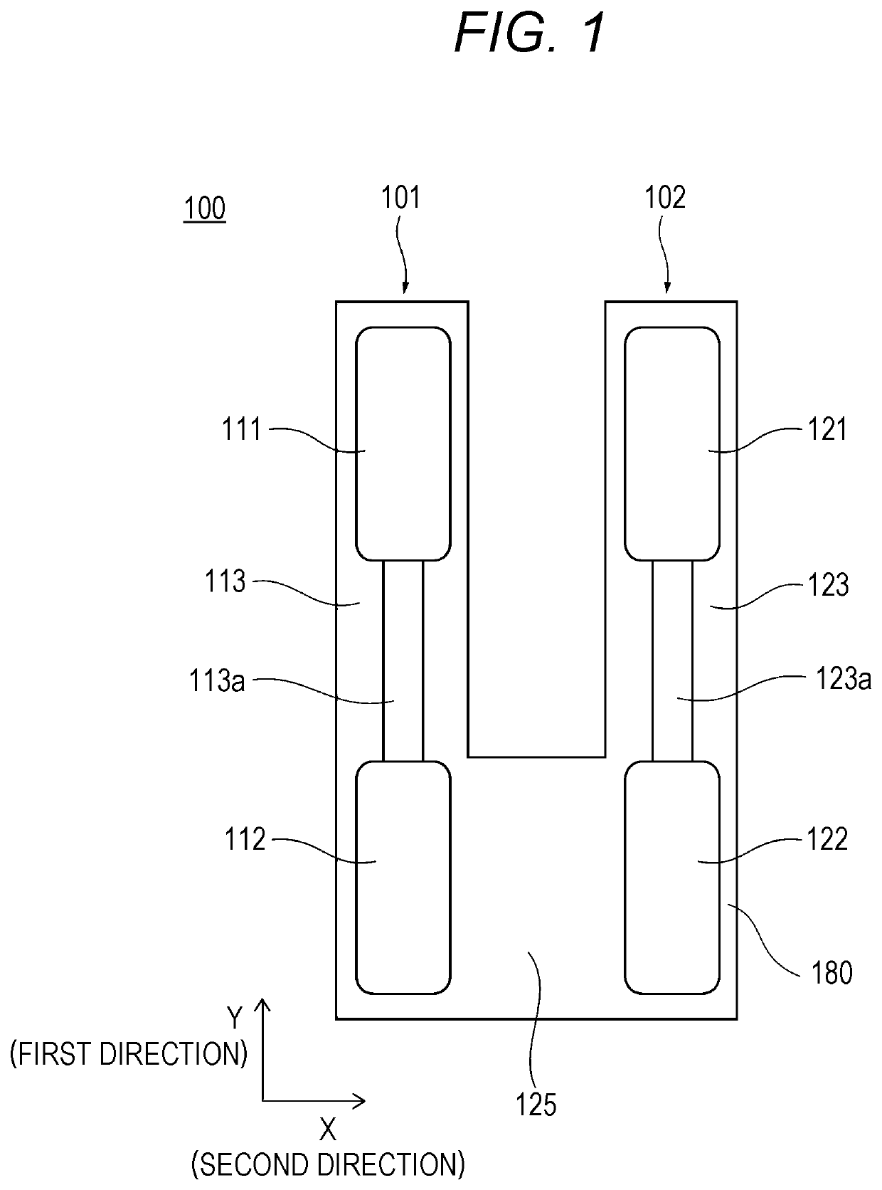
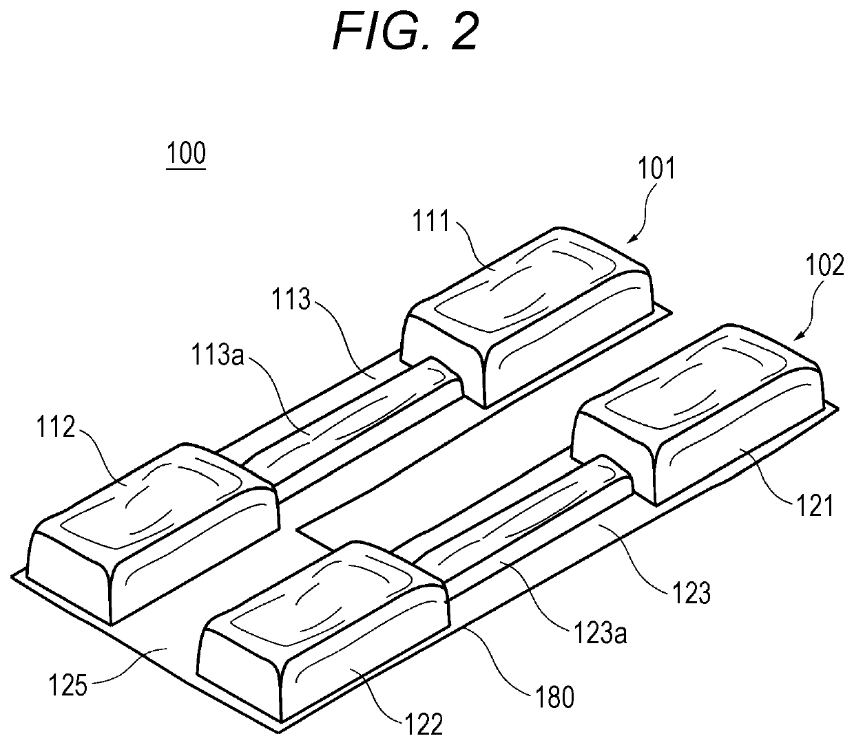
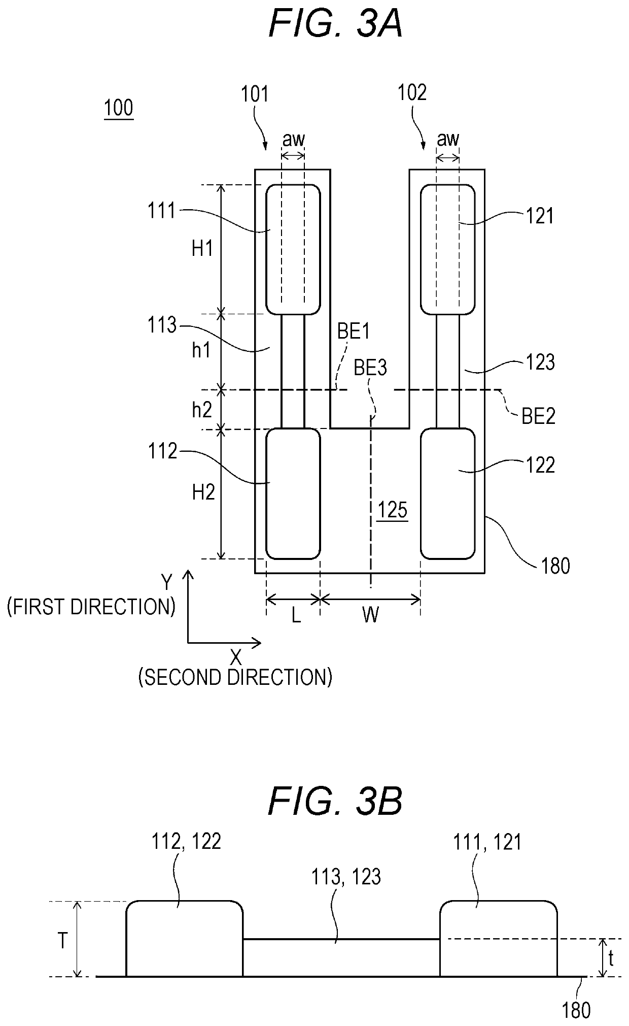
[0064]FIG. 1 is a plan view illustrating a configuration of an air cushioning material of a first embodiment. FIG. 2 is a perspective view illustrating a configuration of the air cushioning material of the first embodiment.
[0065]As illustrated in FIGS. 1 and 2, an air cushioning material 100 of the first embodiment includes a first module 101 and a second module 102.
[0066]In the first module 101, a first air cell 111 and a second air cell 112 each containing air are connected to each other by a first belt-like part 113. The first belt-like part 113 includes an air passage 113a. With the air passage 113a, the air circulates between the first air cell 111 and the second air cell 112. The air passage 113a may not be provided. However, it is preferable that the air passage 113a is provided. With the air passage 113a, the air in one of the first air cell 111 and the second air cell 112 being pressed can move to the other one, so that the air cell can be prevented from rupturing.
[0067]In ...
second embodiment
[0119]FIG. 13 is a plan view illustrating a configuration of an air cushioning material 200 of a second embodiment. FIG. 14 is a perspective view illustrating a configuration of the air cushioning material 200 of the second embodiment.
[0120]As illustrated in FIGS. 13 and 14, the air cushioning material 200 of the second embodiment includes an air passage 125a provided to the coupling part 125 coupling a part of the second air cell 112 of the first module 101 and a part of the fourth air cell 122 of the second module 102. Other configurations are the same as those in the first embodiment. The length of each part is the same as that in the first embodiment. The attachment mode of the air cushioning material 200 to the article 10 is the same as that in the first embodiment. Therefore, descriptions for these will be omitted.
[0121]The air cushioning material 200 of the present second embodiment provides the following effects.
[0122]In the air cushioning material 200 of the present second ...
third embodiment
[0124]FIG. 15 is a plan view illustrating a configuration of an air cushioning material 300 of a third embodiment.
[0125]As illustrated in FIG. 15, a length A1 of the first belt-like part 113 of the air cushioning material 300 of the third embodiment in the second direction is shorter than a length A of the first air cell 111 in the second direction. The second belt-like part 123 has a plurality of belt parts 323 and 324 in the direction connecting the third air cell 121 and the fourth air cell 122. Therefore, the second belt-like part 123 has a space 350 between the belt parts 323 and 324. A length B of the space 350 in the first direction is preferably equal to or greater than the length A of the first air cell 111 in the second direction (B≥A). Thus, in the air cushioning material 300 of the third embodiment, the first air cell 111 can pass through the space 350 formed between the plurality of belt parts 323 and 324.
[0126]Other configurations are the same as those in the first or ...
PUM
 Abstract
Description
Claims
Application Information
 - R&D
- Intellectual Property
- Life Sciences
- Materials
- Tech Scout
- Unparalleled Data Quality
- Higher Quality Content
- 60% Fewer Hallucinations
Browse by: Latest US Patents, China's latest patents, Technical Efficacy Thesaurus, Application Domain, Technology Topic, Popular Technical Reports.
© 2025 PatSnap. All rights reserved.Legal|Privacy policy|Modern Slavery Act Transparency Statement|Sitemap|About US| Contact US: help@patsnap.com


