Hydraulic piston with a depressurized groove

a technology of hydraulic piston and groove, which is applied in the direction of machines/engines, liquid fuel engines, positive displacement liquid engines, etc., can solve the problems of increasing the friction loss generated, the gap between the seal produced by the sliding skirt and the fixed skirt of the hydraulic piston which is equipped with the device is sufficiently leaky, and the effect of eliminating the drawbacks

Active Publication Date: 2021-09-30
RABHI VIANNEY
View PDF9 Cites 0 Cited by
  • Summary
  • Abstract
  • Description
  • Claims
  • Application Information

AI Technical Summary

Benefits of technology

The new design for a hydraulic piston solves problems that previously existed by adding a special feature called a depressurized groove. This helps improve performance and efficiency.

Problems solved by technology

The technical problem addressed in this patent is to improve the sealing device for hydraulic pumps and motors by reducing friction losses and energy losses, especially at high cylinder capacity. The solution involves the use of a sliding skirt and a fixed skirt to create a seal between the piston and the cylinder. However, additional measures such as decompression grooves or increased play between the skirt and the cylinder are needed to ensure the desired seal.

Method used


Image

  • Hydraulic piston with a depressurized groove
  • Hydraulic piston with a depressurized groove
  • Hydraulic piston with a depressurized groove

Examples


Embodiment Construction

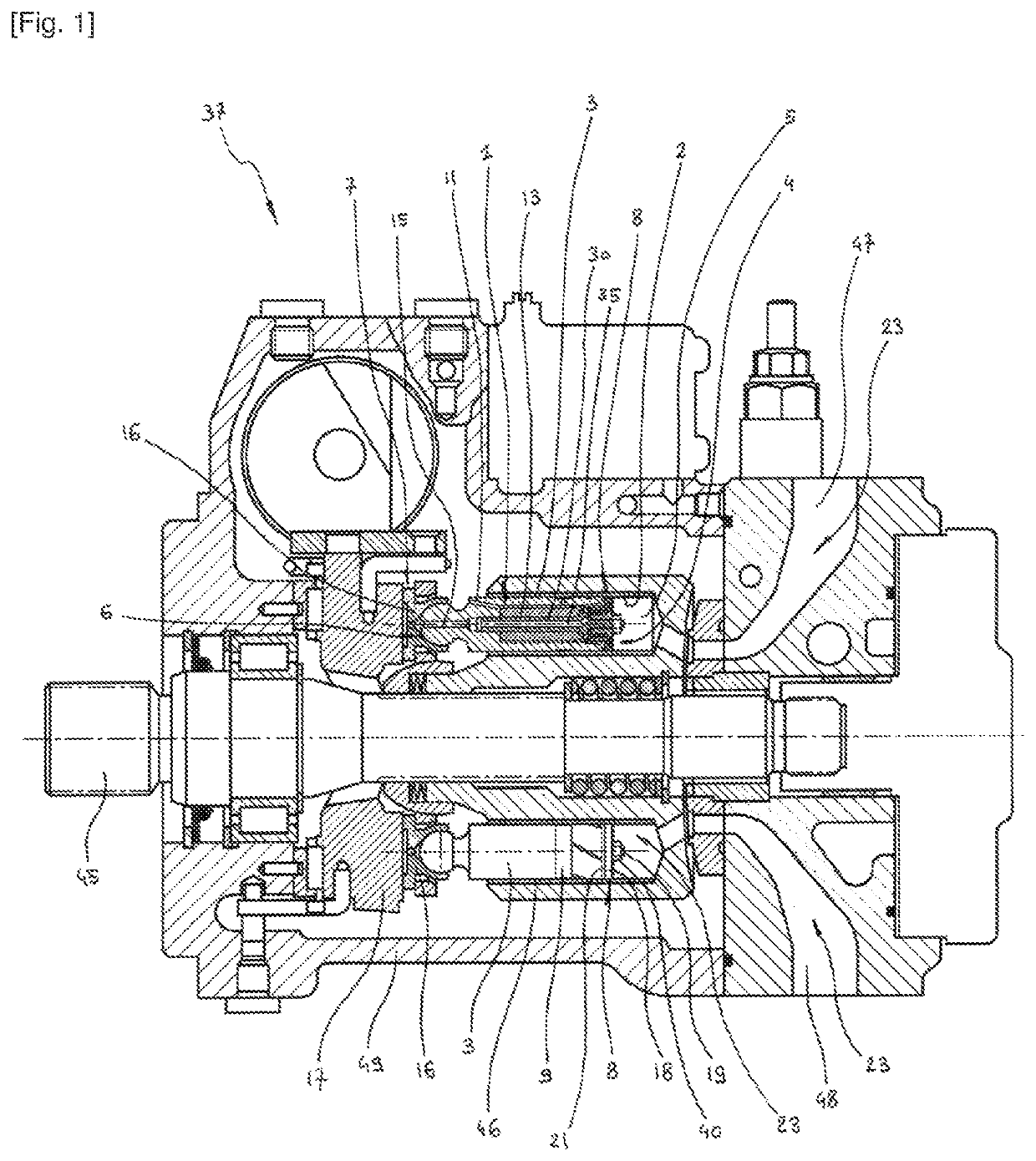
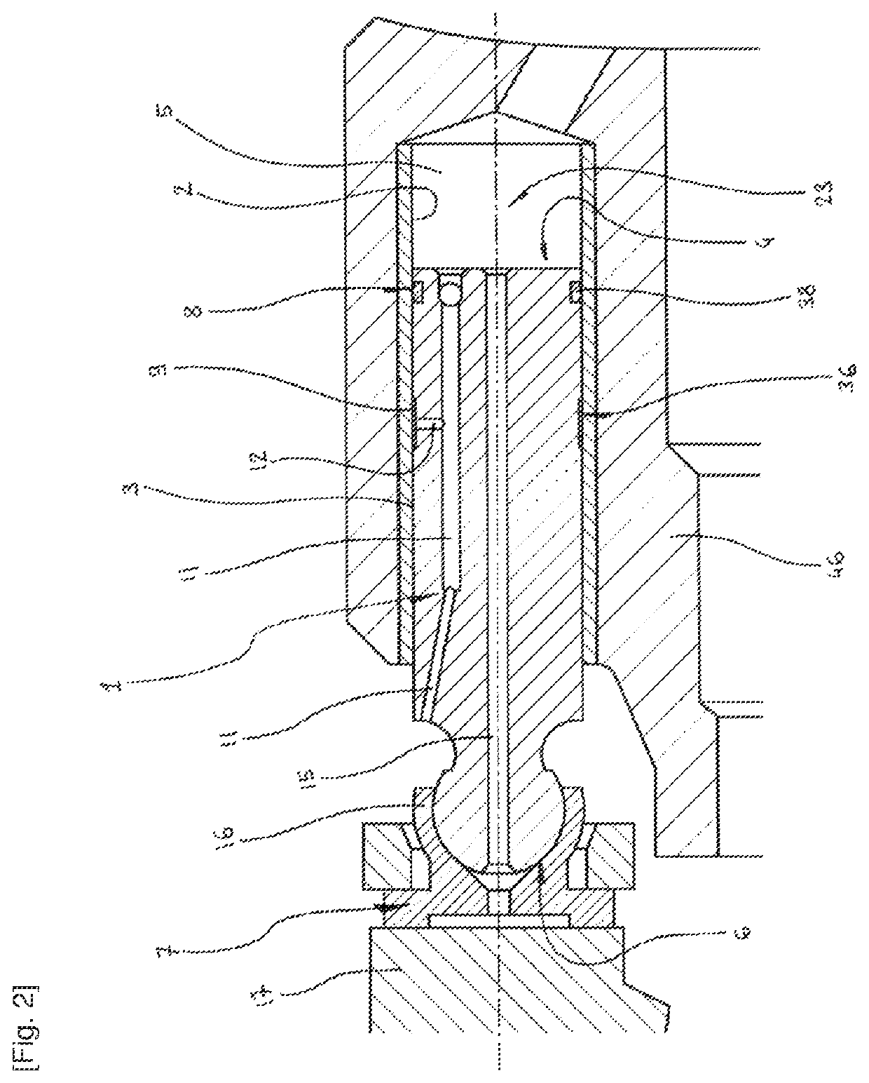
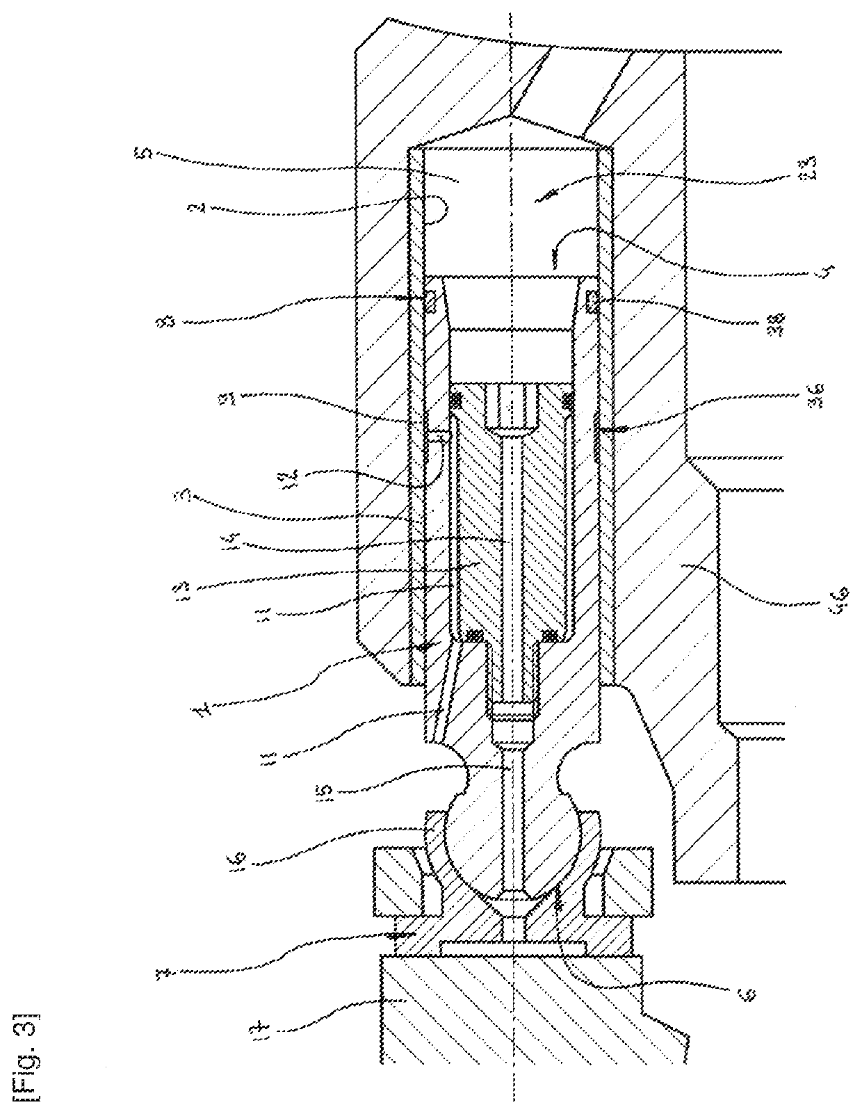
[0072]FIGS. 1 to 10 show the hydraulic piston 1 with a depressurized groove according to the invention, various details of the components thereof, variants thereof, and accessories thereof.

[0073]It can be seen, particularly in FIGS. 1 to 5, that the hydraulic piston 1 with a depressurized groove according to the invention can translate in a cylinder 2, the external cylindrical surface of said piston 1 constituting a fixed skirt 3 while one of the ends of said piston 1 has an axial compression face 4 which forms with the cylinder 2 a fluid chamber 5 of variable volume filled with a working fluid 23, the other end of said piston 1 having an axial working face 6 which cooperates with transmission means 7.

[0074]It is to be noted in FIGS. 1 to 10 that the hydraulic piston 1 with a depressurized groove according to the invention comprises sealing means 8 positioned in the vicinity of the axial compression face 4. Said means 8 are arranged or accommodated either on the fixed skirt 3, or at...


PUM


Abstract

The hydraulic piston with a depressurized groove is capable of translating in a cylinder and includes a fixed skirt, an axial compression face which forms with the cylinder a fluid chamber, and an axial working face which cooperates with a transmission; the piston also includes a seal, a depressurized radial groove emerging onto the surface of the fixed skirt, an axial decompression duct fitted inside the skirt which emerges in the vicinity of the axial working face, and a radial decompression duct which depressurizes the radial groove in communication with the axial decompression conduit.

Description


Claims


Application Information

Patent Timeline
Owner RABHI VIANNEY
Why Eureka
Try Eureka