Single-mode optical fiber having negative chromatic dispersion

a single-mode optical fiber and negative chromatic dispersion technology, applied in the field of single-mode optical fibers, can solve the problems of increasing the chromatic dispersion penalty of the channel, requiring equipment-intensive grating fabrication and overgrowth deposition steps, and significant large chromatic dispersion penalties, so as to reduce the chromatic dispersion, reduce the multi-path interference (mpi), and increase the power margin

Pending Publication Date: 2021-09-23
PANDUIT
View PDF0 Cites 0 Cited by
  • Summary
  • Abstract
  • Description
  • Claims
  • Application Information

AI Technical Summary

Benefits of technology

[0011]Disclosed is modifications to the optical waveguide attributes of SMF to make the fiber more compatible with low-cost, high-speed optical transceivers for short reach applications utilizing lasers in the 1310 nm window (O-band). Modifications to the SMF optical attributes include shifting the zero-dispersion wavelength (ZDW) to reduce chromatic dispersion due to laser chirp, and, shifting the cutoff wavelength (xc) to reduce multipath interference (MPI). Single-mode fibers in accordance with the present invention provide increased power margins for improved channel reliability and / or longer channel reach for transceivers operating in the 1310 nm window.

Problems solved by technology

This broad signal linewidth results in a significantly large chromatic dispersion penalty.
Today, for high-speed WDM applications, distributed-feedback (DFB) semiconductor lasers are used, but the manufacturing process requires equipment-intensive grating fabrication and overgrowth deposition steps.
Although in principle DFB lasers are single-frequency devices, due to a phenomenon known as laser chirp, DFB lasers have a narrow but finite spectral width which increases the channel chromatic dispersion penalty, thereby contributing to the limitation in maximum channel reach.
As the input signal drive current enters the laser cavity, the increase in charge density results in an increase in material refractive index, which in turn monotonically reduces the transmitted optical wavelength.

Method used


Image

  • Single-mode optical fiber having negative chromatic dispersion
  • Single-mode optical fiber having negative chromatic dispersion
  • Single-mode optical fiber having negative chromatic dispersion

Examples


Embodiment Construction

[0019]An optical fiber in accordance to the present invention has a zero-dispersion wavelength shifted to a longer wavelength compared to industry Standards unshifted single-mode fiber Types IT U-G.652, and / or IT U-G.657, where the ZDW is specified to be between 1302 nm and 1322 nm. A fiber compliant with the present invention has a ZDW greater than 1334 rnm, so that essentially all transmitted operating wavelengths in the 1310 nm window undergo a negative chromatic dispersion when propagating through said optical SMF channel. A negative dispersion compensates for the chromatic dispersion due to laser chirp, thereby reducing the signal pulse-width and hence, the dispersion penalty of the channel.

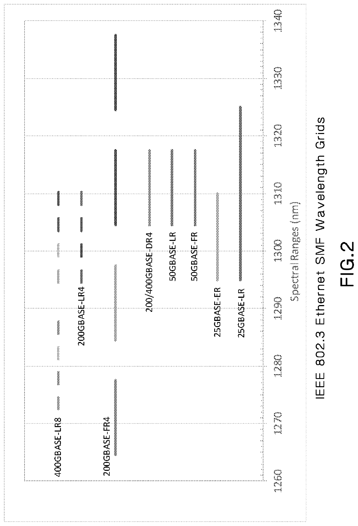
[0020]In FIG. 2, we plot the spectral grids and wavelength ranges for 8 SMF laser transceiver options specified in IEEE 802.3 Ethernet Standards for data rates ranging from 25 Gb / s to 400 Gb / s. Transceivers can include 1, 4, or 8 discrete signal wavelengths. For these Ethernet specified tran...


PUM

PropertyMeasurementUnit
cable cutoff wavelengthaaaaaaaaaa
zero-dispersion wavelengthaaaaaaaaaa
mode field diameteraaaaaaaaaa

Abstract

A single-mode optical fiber that reduces the chromatic dispersion of an optical pulse due the laser chirp in an optical communication system operating in the O-band has a cable cutoff wavelength less than 1250 nm, a zero-dispersion wavelength greater than 1334 n, and a nominal mode field diameter of said fiber at 1310 nm between 8.6 and 9.5 microns.

Description

CROSS REFERENCE TO RELATED APPLICATION[0001]This application claims priority to U.S. Provisional Application No. 62 / 696,973, filed Jul. 12, 2018, the subject matter of which is hereby incorporated by reference in its entirety.FIELD OF THE INVENTION[0002]The invention generally relates to optical fibers and specifically to single mode optical fibers for reducing chromatic dispersion.BACKGROUND OF THE INVENTION[0003]Today, the requirements for high-speed optical communications is primarily driven by the bandwidth demands of hyperscale data center networks, where channel reaches are short and range from 2 to 500 m. For data rates of 100 Gb / s and higher, the maximum channel reach over laser optimized OM4 or OM5 multimode fiber, as specified in IEEE 802.3 Ethernet Standards, is 100 m. Single-mode transceivers are specified to operate in the O-Band and support channel reaches of 2 km or 10 km, depending on the transceiver option. As the maximum channel reach of MMF continues to decrease, ...

Claims


Application Information

Patent Timeline
Patent Type & Authority Applications(United States)
IPC IPC(8): G02B6/02H04B10/2525
CPCG02B6/02252H04B10/2525G02B6/02214
Inventor PIMPINELLA, RICHARD J.CASTRO, JOSE M.KOSE, BULENTNOVICK, ASHER S.HUANG, YU
Owner PANDUIT
Why Eureka
Try Eureka