
Stop sign with traffic control features

a technology of traffic control and stop sign, which is applied in the direction of traffic control of road vehicles, traffic detection, instruments, etc., can solve the problems of high cost of installation at every intersection, frequent traffic congestion, and high cost of traffic collisions, so as to improve traffic flow and reduce accidents

Pending Publication Date: 2021-08-26
LAMONCHA MARK
View PDF25 Cites 3 Cited by
  • Summary
  • Abstract
  • Description
  • Claims
  • Application Information

AI Technical Summary

Benefits of technology

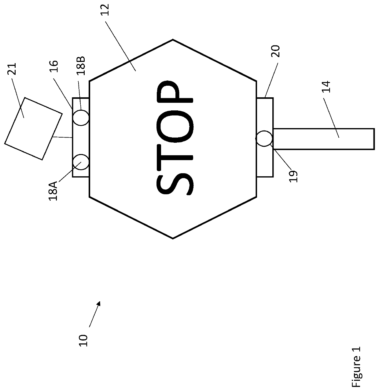
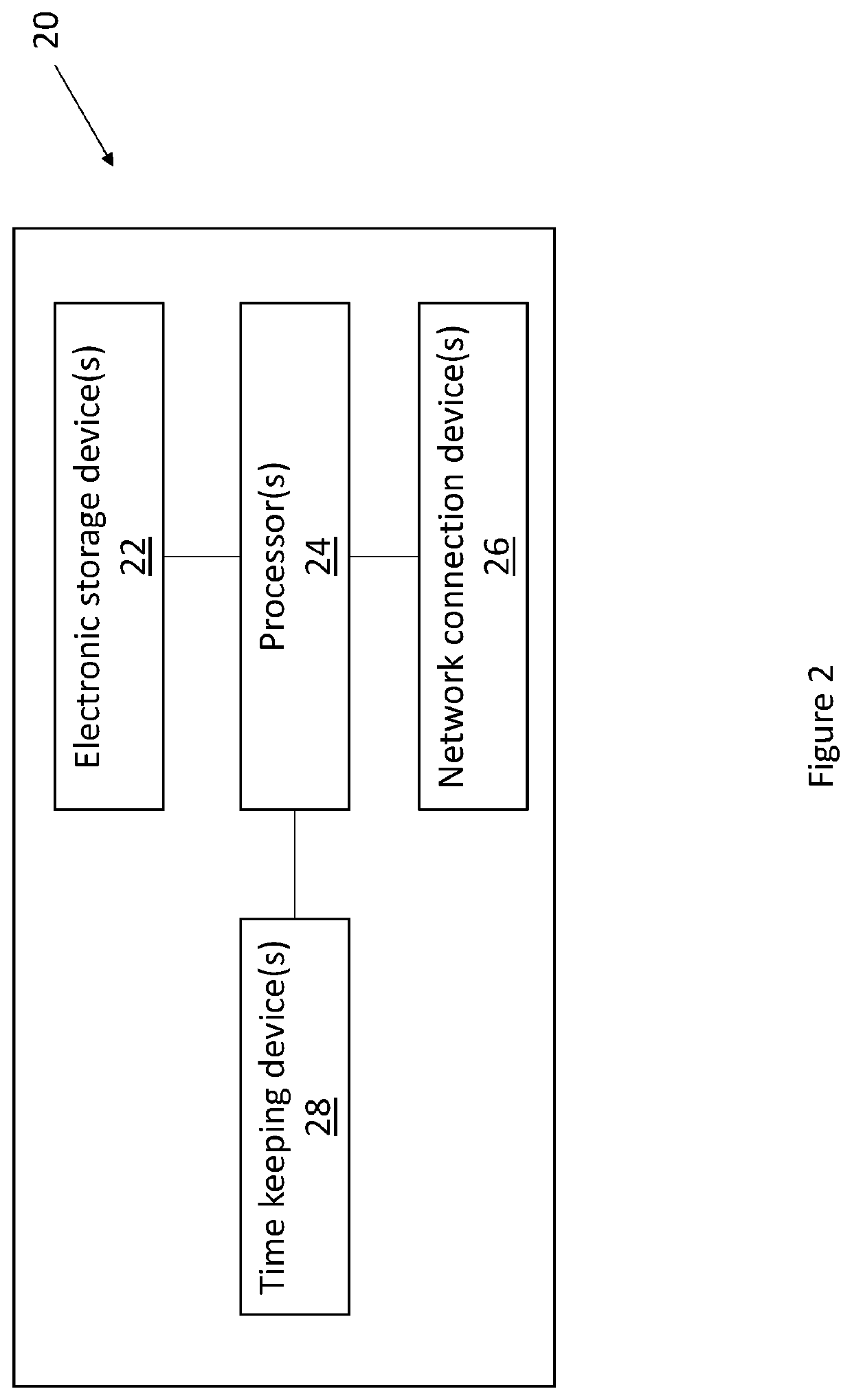
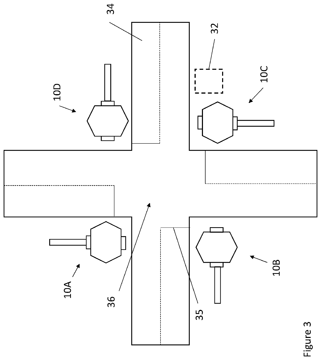
This patent describes a stop sign with traffic control features that can help alleviate traffic congestion at roadintersections. The stop sign has a traffic control unit that can direct drivers on which way to go based on the traffic conditions at the intersection. It uses various sensors and devices to detect vehicles, and a controller to guide the traffic. The invention can also communicate traffic signals to a driver's vehicle based on the vehicle's own system or a central command unit. This can help prevent accidents and reduce delays for drivers. The invention can be used in both vehicles that have the traffic control system and vehicles without it.

Problems solved by technology

Traffic congestion is frequently caused by roadway intersections.
Traffic often becomes backed up at intersections where conventional stop signs are used to control traffic because drivers are unsure of which driver has the right of way to cross the intersection first.
Furthermore, traffic collisions often occur when one driver proceeds despite not having the right of way.
While traffic lights can provide for improved traffic flow and reduced accidents, they are too expensive to install at every intersection.
Furthermore, stop signs are not adaptable to changing traffic conditions.
This may result in running of red lights, running of stop signs, or collisions.
Even where there is merely a delay by the distracted driver in noticing a changing traffic signal, traffic delays, confusion for other drivers, and the like may result.
If the driver attempts to proceed during a wait signal, the vehicle interface system may cause the vehicle to slow or stop.

Method used


Image

  • Stop sign with traffic control features
  • Stop sign with traffic control features
  • Stop sign with traffic control features

Examples


Embodiment Construction

)

[0031]Various embodiments of the present invention will now be described in detail with reference to the accompanying drawings. In the following description, specific details such as detailed configuration and components are merely provided to assist the overall understanding of these embodiments of the present invention. Therefore, it should be apparent to those skilled in the art that various changes and modifications of the embodiments described herein can be made without departing from the scope and spirit of the present invention. In addition, descriptions of well-known functions and constructions are omitted for clarity and conciseness.

[0032]Embodiments of the invention are described herein with reference to illustrations of idealized embodiments (and intermediate structures) of the invention. As such, variations from the shapes of the illustrations as a result, for example, of manufacturing techniques and / or tolerances, are to be expected. Thus, embodiments of the invention ...


PUM


Abstract

Systems and methods for controlling traffic at an intersection are provided. A controller receives data from a vehicle detection device indicating a presence or non-presence of vehicles within a first area forward or adjacent to the stop sign. The controller receives data from a cross-traffic vehicle detection device indicating a presence or non-presence of vehicles within a second area rearward of the stop sign. Where data is received indicating the presence of at least one vehicle within the first area and the non-presence of any vehicles within the second area, the controller commands a traffic signaling device for the stop sign to temporarily cease providing the wait signal and instead provide the proceed signal.

Description

CROSS-REFERENCE TO RELATED APPLICATION[0001]This application is a continuation-in-part of U.S. application Ser. No. 17 / 201,266 filed Mar. 15, 2021, which is a continuation-in-part of U.S. application Ser. No. 17 / 158,365 filed Jan. 26, 2021, which is a continuation of U.S. application Ser. No. 16 / 682,723 filed Nov. 13, 2019, which claims the benefit of U.S. Provisional Application No. 62 / 769,034 filed Nov. 19, 2018, the disclosures of each of which are hereby incorporated by reference as if fully restated herein.TECHNICAL FIELD[0002]Exemplary embodiments of the present invention relate generally to systems and methods for controlling traffic using a stop sign with traffic control features.BACKGROUND AND SUMMARY OF THE INVENTION[0003]Traffic congestion is frequently caused by roadway intersections. Traffic often becomes backed up at intersections where conventional stop signs are used to control traffic because drivers are unsure of which driver has the right of way to cross the inter...

Claims


Application Information

Patent Timeline
IPC IPC(8): G08G1/01G08G1/04G08G1/085
CPCG08G1/0116G08G1/085G08G1/04G08G1/095
Inventor LAMONCHA, MARK
Owner LAMONCHA MARK
Learn More