Portable image pickup apparatus
a technology of image pickup and attachment device, which is applied in the field of image pickup apparatus, can solve the problems of difficult holding of the camera, and achieve the effect of convenient attachment and detachment and high portability
- Summary
- Abstract
- Description
- Claims
- Application Information
AI Technical Summary
Benefits of technology
Problems solved by technology
Method used
Image
Examples
first embodiment
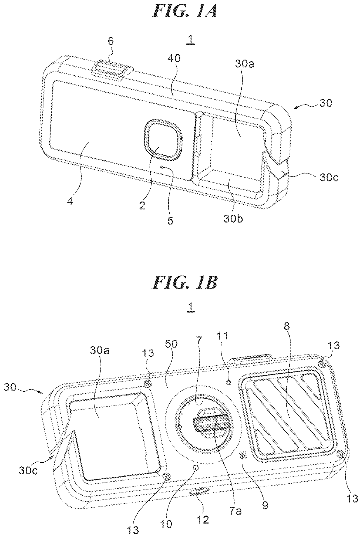
[0024]FIG. 1A is an external perspective view showing a digital camera 1 as an example of an image pickup apparatus concerning a first embodiment viewed from a front side (an object side). FIG. 1B is an external perspective view showing the digital camera 1 viewed from an opposite side (a rear side) of an object.
[0025]The digital camera 1 has a front cover 40, a rear cover 50, and an image pickup lens 2. The front cover 40 and rear cover 50 are tightened and fixed with screws 13, and the front cover 40 and the rear cover 50 that are tightened constitute an exterior of the digital camera 1. A tripod hole 12 is formed in a bottom surface of the exterior of the digital camera 1.
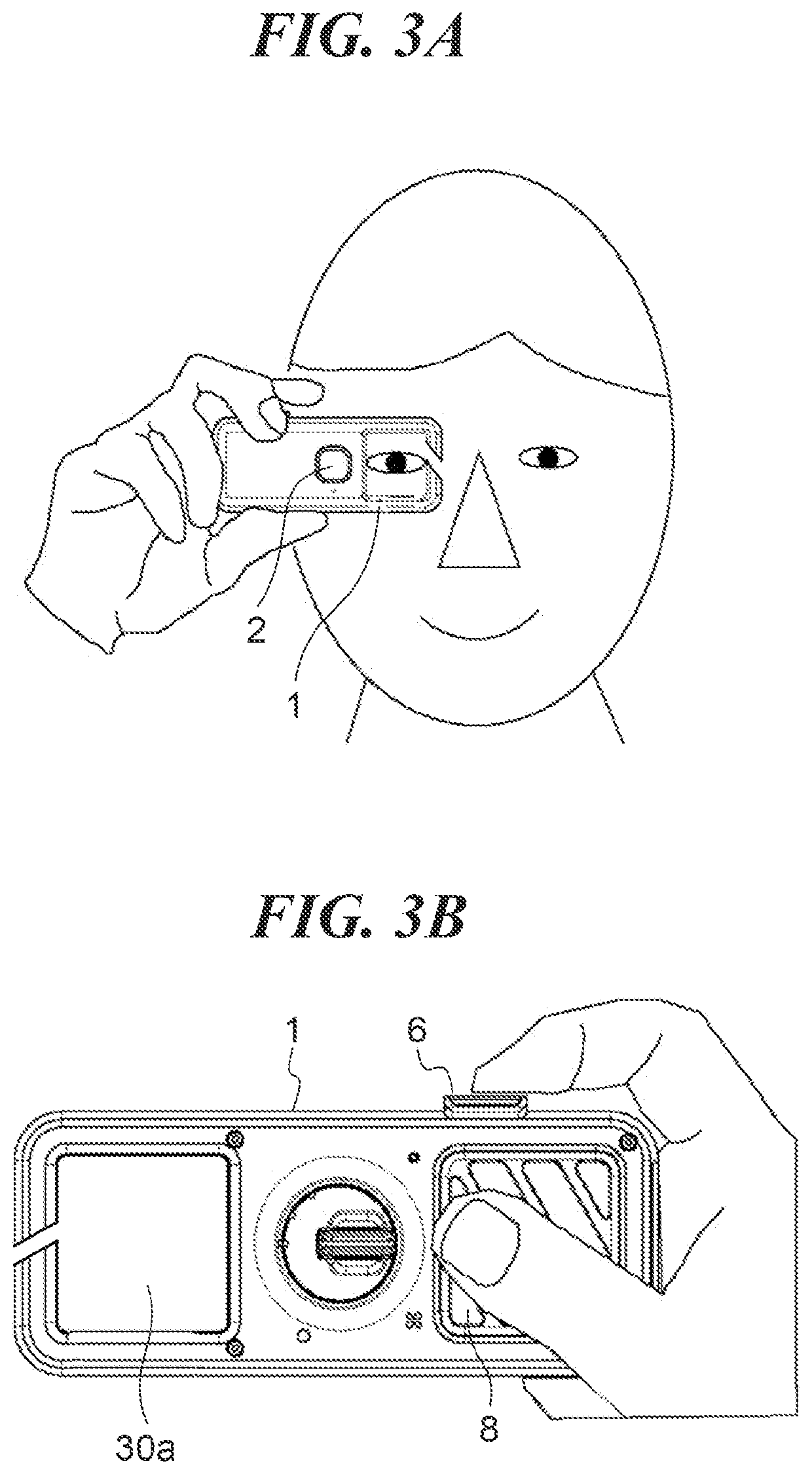
[0026]A rectangular frame part is formed in one end of the digital camera I in a longitudinal direction. This frame part is used to attach the digital camera 1 to mounted members (not shown), such as clothing like a belt loop of trousers of a user, a belt of a rucksack, and a stop ring attached at a predetermine...
second embodiment
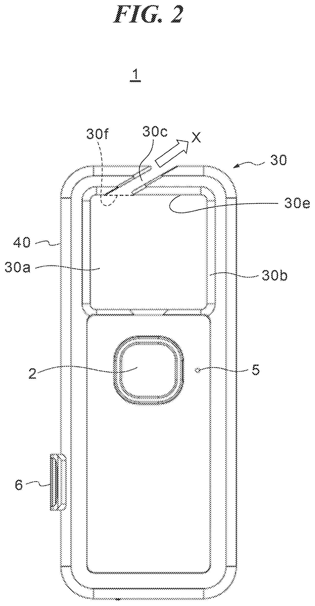
[0053]FIG. 5A is a front view schematically showing a configuration of a digital camera 1A of a first example concerning the The digital camera 1A has a notch section 30c that is formed by cutting out the attachment part 30 at a section that intersects perpendicularly with the mounted-member contact surface 30e in a direction that is approximately identical to the operation direction of the release button 6. In this way, since the notch section 30c is arranged at the position different from the mounted-member contact surface 30e to which a mounted member (not shown) contacts to support the digital camera 1A in a state where the attachment part 30 is attached to the mounted member, the mounted member hardly contacts the notch section 30c. Accordingly, even if a user hangs the digital camera 1A to a belt loop of trousers, a belt of a rucksack, or the like, the digital camera 1A does not depart easily (carelessly). Although the notch section 30c of the digital camera 1A is arranged on...
third embodiment
[0074]FIG. 9A is an external perspective view showing a digital camera 1E of a second example of the third embodiment viewed from the front side and shows a state where an attachment part 300 is in a first position. FIG. 9B is an XY sectional view corresponding to the state of FIG. 9A. FIG. 9C is an external perspective view showing the digital camera 1E in a state where the attachment part 300 is in a second position viewed from the front side. FIG. 9D is an XY sectional view corresponding to the state of FIG. 9C.
[0075]The digital camera 1D of the first example is constituted so that the attachment part 300 is slidable as a whole. In the meantime, the attachment part 300 of the digital camera 1E of the second example consists of a stationary member 40b and a movable member 301 that is slidable. Hereinafter, this difference will be described mainly. Moreover, the same reference numerals are applied to components of the digital camera 1E identical to the components of the digital cam...
PUM
 Abstract
Description
Claims
Application Information
 - R&D
- Intellectual Property
- Life Sciences
- Materials
- Tech Scout
- Unparalleled Data Quality
- Higher Quality Content
- 60% Fewer Hallucinations
Browse by: Latest US Patents, China's latest patents, Technical Efficacy Thesaurus, Application Domain, Technology Topic, Popular Technical Reports.
© 2025 PatSnap. All rights reserved.Legal|Privacy policy|Modern Slavery Act Transparency Statement|Sitemap|About US| Contact US: help@patsnap.com


