Blow molded article with visual effects

a blow molding and visual effect technology, applied in the field of blow molding articles, can solve the problems of increasing the difficulty of large-scale blow molding operations, reducing the effect of blow molding,

Pending Publication Date: 2021-07-22
PROCTER & GAMBLE CO
View PDF4 Cites 3 Cited by
  • Summary
  • Abstract
  • Description
  • Claims
  • Application Information

AI Technical Summary

Benefits of technology

The invention provides hollow containers that are resistant to delamination, which is a common problem in the manufacturing of blow molded multilayer hollow articles such as containers. The containers have a strong connection between the layers, even without any adhesive at the interface, which makes it difficult for the layers to separate and causes bubbles and / or rippling to appear underneath the outer surface. The use of parallel flow coinjection results in prolonged contact of the materials of the various layers still in melted or partially melted state, which forms a transition region between the layers.

Problems solved by technology

However the introduction of effect pigments in large scale blow molding operations has been found to be more problematic and in fact effect pigments do not find a broad industrial application in this field, especially when considering containers for liquid products which need to be mass produced quickly and at a low cost.
Effect pigments can be applied on blow molded articles using standard coating application techniques such as painting or printing, however this adds complexity, costs and additional problems such as need for lacquering which are not realistic in the mass production of blow molded articles.
One relevant issue in in the introduction of effect pigments within a blow molding manufacturing process is that the pigment particles remain dispersed within the wall of the article in a largely random orientation so that their effect is reduced.
An additional problem (partially connected to the poor orientation of the particles in a blow molded article) is that blow molded articles comprising effect pigments have been found to have poor gloss and high haze.
Without being bound by theory it is believed this is due to the unevenness of the external surface of the articles when effect pigments are present possibly due to the random orientation of the platelet particles which in part will be exposed at the surface of the article in all orientations.
However, we have observed that in certain cases such construction method leads to poor mechanical properties of the finished article, so that the layers may separate during use (delamination).

Method used


Image

  • Blow molded article with visual effects
  • Blow molded article with visual effects
  • Blow molded article with visual effects

Examples


examples

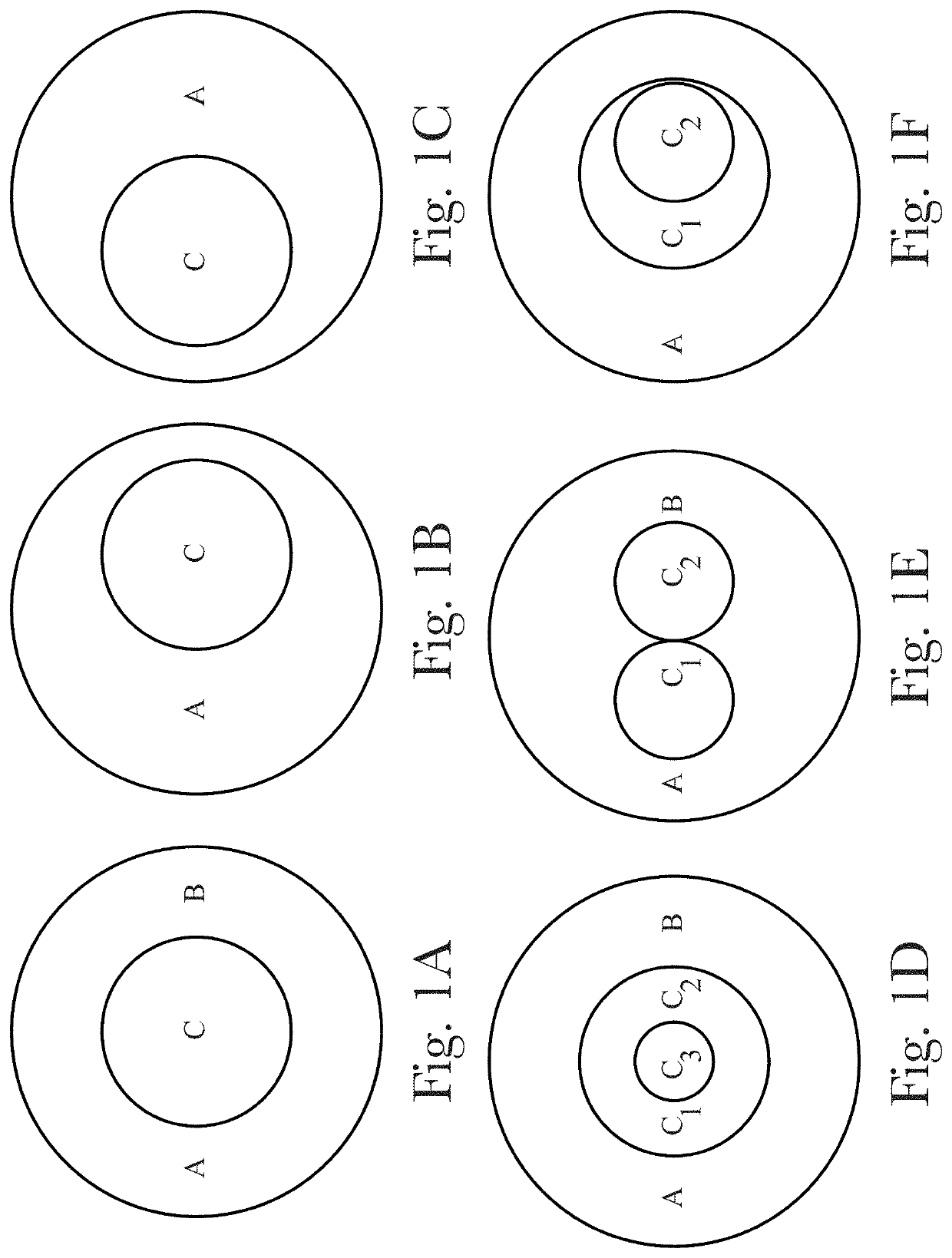
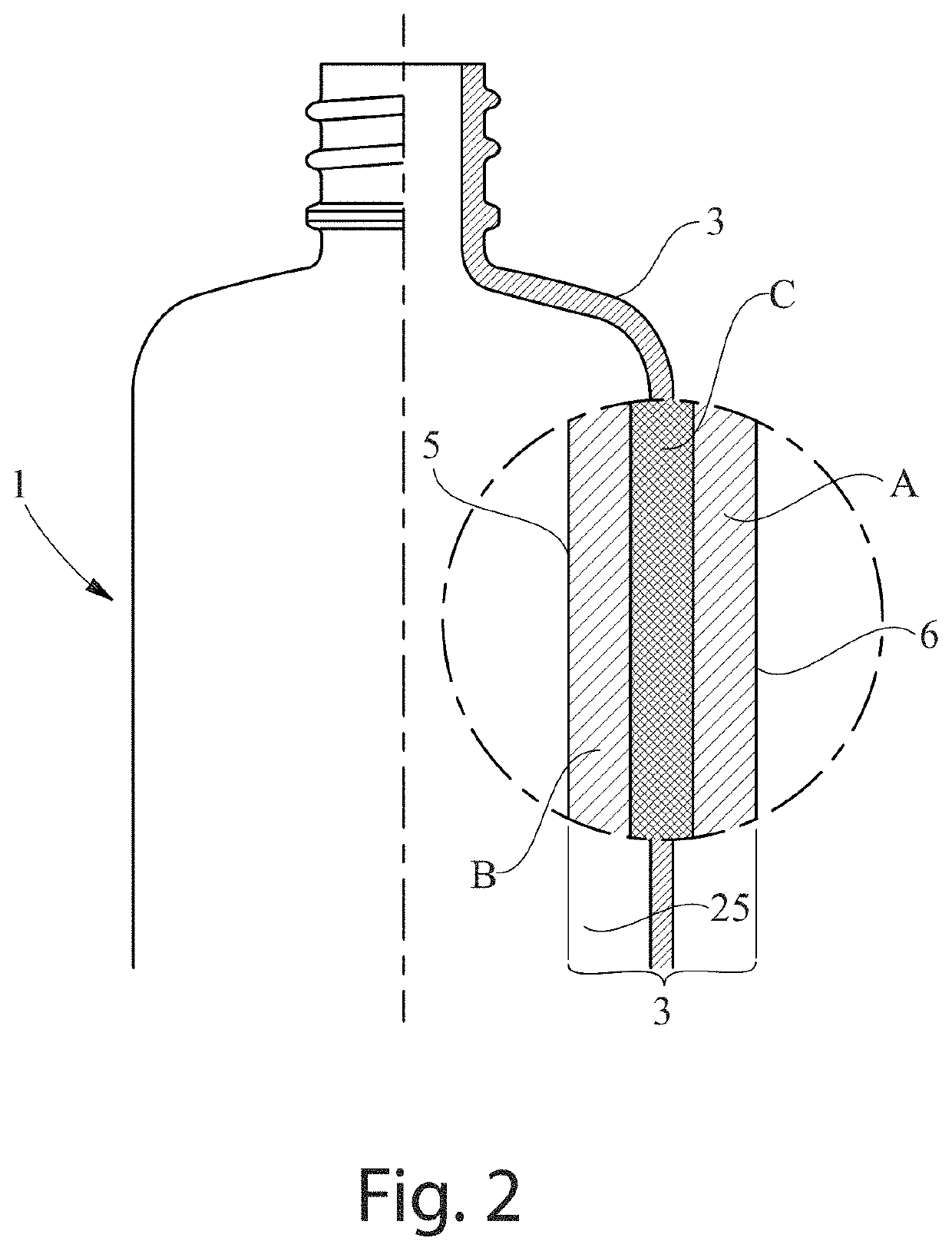
[0134]Several bottles were prepared, Ex. 1-3 are according to the invention, Ex. 4-9 are comparative examples. These examples are described in Table 4 to Table 6, below. In the example with three layers, layer A comprises the outer surface, layer B comprises the inner surface, and layer C is located between layers A and B.

TABLE 4ExamplesEx. 1Ex. 2Ex. 3Layer APET + 2% transparentPET + 3% transparentPET + 2% transparentorange masterbatchgold masterbatchgreen masterbatchLayer CPET + 4% White PearlPET + 4% White PearlPET + 4% White Pearlsatin masterbatchsatin masterbatchsatin masterbatchLayer BPET + 2% transparentPET + 3% transparentPET + 2% transparentorange masterbatchgold masterbatchgreen masterbatchThickness ofA = 170 A = 145A = 170layer (μm)C = 160C = 60C = 160B = 70 B = 95B = 70 PreformParallel co-injectionParallel co-injectionParallel co-injectionTechnology

TABLE 5Comparative ExamplesEx. 4Ex. 5Ex. 6Layer APET + 5% opaquePET + 2% transparentPET + 5% opaquewhite masterbatchorange ma...


PUM

PropertyMeasurementUnit
volumesaaaaaaaaaa
volumesaaaaaaaaaa
volumesaaaaaaaaaa

Abstract

A blow molded article obtained by blow molding of a preform made via parallel flow coinjection, having a wall formed by 3 layers in at least a region wherein the outside layer is transparent and the inner layer comprises an effect pigment visible through the transparent layer. Articles according to the invention have an improved gloss, low haze and higher resistance to delamination than previous articles. The invention relates also to preforms for making articles as described and to methods for making preforms and articles.

Description

FIELD OF THE INVENTION[0001]The present invention relates to blow molded articles with effect pigments showing high gloss, low haze and high resistance to delamination. The invention relates also to preforms for making such articles and to methods for making these preforms and articles.BACKGROUND OF THE INVENTION[0002]Blow molded articles made of thermoplastic materials such as polyethylene terephthalate (PET) and obtained from stretch blow molding of an injected preform (injection stretch blow molded articles, also called ISBM articles) are popularly used in various industries, including the cosmetic, laundry, and food industries. In particular, containers for such fields and in particular bottles for liquid products are made in this way. For such articles, having a glossy and pearlescent and / or metallic appearance is particularly desirable as it is appealing to users and tends to connote a premium product.[0003]In order to obtain such appearance so called “effect pigments” have be...

Claims


Application Information

Patent Timeline
Patent Type & Authority Applications(United States)
IPC IPC(8): B65D1/02B29C49/06B29B11/14B29C49/22
CPCB65D1/0215B29C49/06B29K2105/0032B29C49/221B29B11/14B29K2995/002B29C2949/3018B29C2949/3036B29C49/071B29C2949/0715B29C2049/023Y10T428/139Y10T428/1393Y10T428/1352B29C2949/3032B29K2995/0018B29K2067/003B29L2031/7158
Inventor NEUFARTH, BRADLEY SCOTTHORTON, ANDREW JOSEPHMAMAK, MARC ANDREWAGERTON, MARK LEWISSAWIN, PHILIP ANDREWCONSTANTINIDES, IOANNIS CONSTANTINE
Owner PROCTER & GAMBLE CO
Why Eureka
Try Eureka