
Configuration of robots in multi-robot operational environment

a multi-robot, robot technology, applied in the field of robot configuration, can solve the problems of difficult and time-consuming implementation, not producing an optimized, and affecting the operation efficiency of the robot, so as to reduce the wait time of the robot, reduce the energy consumption or expenditure, and maximize the use of the floor space.

Active Publication Date: 2021-07-22
REALTIME ROBOTICS INC
View PDF0 Cites 3 Cited by
  • Summary
  • Abstract
  • Description
  • Claims
  • Application Information

AI Technical Summary

Benefits of technology

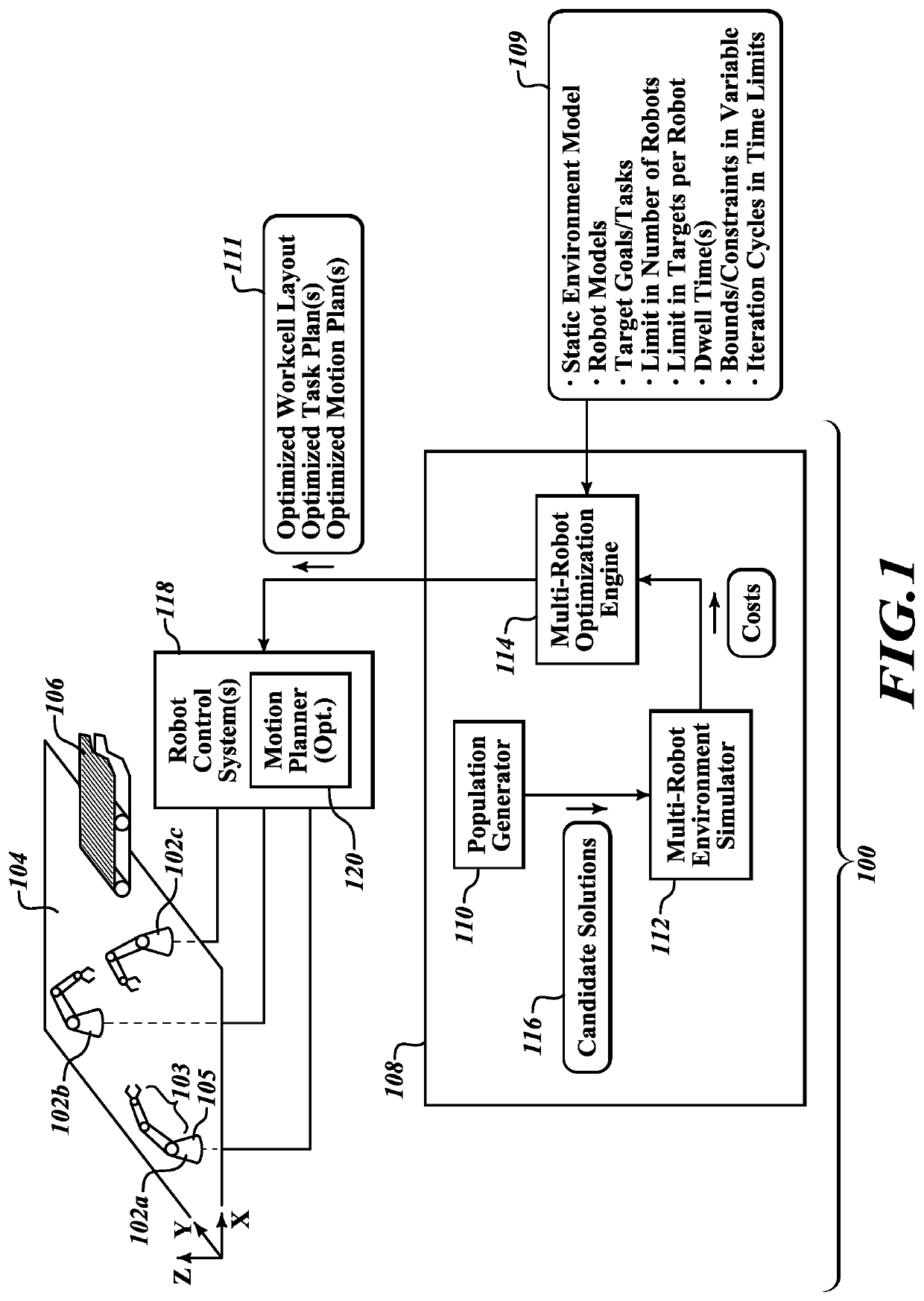
This patent describes a system that optimizes the placement and operation of multiple robots in a workspace, reducing the risk of collisions and increasing efficiency. The system takes into account parameters such as the robots' base position and orientation, task allocation, and target sequences. This approach reduces programming effort and allows for dynamic allocation of tasks. The system also considers latency, floor space, energy consumption, and other factors when making recommendations. Overall, the system helps robots work more efficiently in shared workspace.

Problems solved by technology

Motion planning is a fundamental problem in robot control and robotics.
The operation of two or more robots in a multi-robot operation environment or shared workspace (workspaces are commonly referred to as workcells), present a particular class of problems.
This approach is intuitive, simple to understand, but typically difficult and time consuming to implement, and may not produce an optimized result.
This approach necessarily has low work throughput since the use of task-level de-confliction usually leads to at least one of the robots being idle for significant portions of time, even if it would technically be possible for the idle robot to be performing useful work in the shared workspace.
This may employ iteratively simulating motion to ensure that the robots / robotic appendages do not collide with one another, which may take many hours of computation time, and may not result in an optimized solution.
Such approaches are of course not optimal, and typically require experts to go through the slow process of iteratively trying to find a combination of solutions that, when taken together produces a good result.

Method used


Image

  • Configuration of robots in multi-robot operational environment
  • Configuration of robots in multi-robot operational environment
  • Configuration of robots in multi-robot operational environment

Examples


example 1

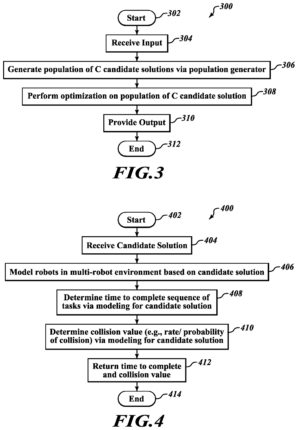
[0135]A method of operation in a processor-based system to configure a plurality of robots for a multi-robot operational environment in which a plurality of robots will operate, the method comprising:

[0136]generating a population of C candidate solutions via a population generator, each of the candidate solutions in the population of C candidate solutions specifying for each of the robots: a respective base position and orientation, a respective set of at least one defined pose, and a respective task or target sequence, where the respective base position and orientation specify a respective position and orientation for a base of the respective robot in the multi-robot operational environment, the respective set of at least one defined pose specifies at least a respective home pose of the respective robot in the multi-robot operational environment, and the respective task or target sequence comprises a respective ordered list of targets for the respective robot to move through to com...

example 2

[0139]The method of example 1 wherein providing as output: the respective base position and orientation for each of the robots, a respective task allocation for each of the robots, and a respective motion plan for each of the robots includes providing an optimized task allocation that specifies, for each robot, a respective sequence of tasks to be performed in the form of an optimized ordered list of targets in C-space of the respective robot and one or more dwell time durations at one or more of the targets, and providing an optimized motion plan that specifies a set of collision-free paths, the set of collision-free paths specifying a respective collision-free path between each pair of consecutive targets in the ordered list of targets.

example 3

[0140]The method of any of examples 1 or 2, further comprising:

[0141]for each of the candidate solutions of the population C of candidate solutions, determining a respective time to complete the sequences of tasks and a respective collision value that represents a rate or a probability of a collision occurring in completing the sequences of tasks via modeling performed by a robot environment simulator.


PUM


Abstract

Solutions for multi-robot configurations are co-optimized, to at least some degree, across a set of non-homogenous parameters based on a given set of tasks to be performed by robots in a multi-robot operational environment. Non-homogenous parameters may include two or more of: the respective base position and orientation of the robots, an allocation of tasks to respective robots, respective target sequences and / or trajectories for the robots. Such may be executed pre-runtime. Output may include for each robot: workcell layout, an ordered list or vector of targets, optionally dwell time durations at respective targets, and paths or trajectories between each pair of consecutive targets. Output may provide a complete, executable, solution to the problem, which in the absence of variability in timing, can be used to control the robots without any modification. A genetic algorithm, e.g., Differential Evolution, may optionally be used in generating a population of candidate solutions.

Description

TECHNICAL FIELD[0001]The present disclosure generally relates to robot configuration in a multi-robot operation environment or shared workspace, and to the optimization of robot configuration in such an environment or shared workspace.BACKGROUNDDescription of the Related Art[0002]Various applications employ or may wish to employ two or more robots in a multi-robot operational environment that is common to, or otherwise shared by, two or more robots. The multi-robot operational environment may take the form of a shared workspace. For example, two or more robots may be employed in performing tasks on or with one or more objects or work pieces in a common operational environment, for instance threading bolts to a chassis where the robots may overlap in range of motion.[0003]Motion planning is a fundamental problem in robot control and robotics. A motion plan specifies a path that a robot can follow from a starting state to a goal state, typically to complete a task without colliding wi...

Claims


Application Information

Patent Timeline
Patent Type & Authority Applications(United States)
IPC IPC(8): B25J9/16G06N3/12
CPCB25J9/1666G06N3/126B25J9/1682B25J9/1669G05B2219/40629G05B2219/40476G05B2219/40417G05B2219/40515G06N5/01
Inventor COLASANTO, LUCAMURRAY, SEAN
Owner REALTIME ROBOTICS INC
Learn More