
Froth flotation apparatus

Pending Publication Date: 2021-07-08
MINTEK
View PDF0 Cites 1 Cited by
  • Summary
  • Abstract
  • Description
  • Claims
  • Application Information

AI Technical Summary

Benefits of technology

The patent text describes a device called a contactor which helps to produce a high gas hold-up in a tank for the purpose of promoting a froth flotation process. The design of the contactor minimizes the likelihood of the mineral feed being directed to the tank's tailings outlet, and uses a baffle to create a vortex in the tank to help distribute the aerated mineral stream. The text also suggests preconditioning the mineral stream with reagents to make the flotation process more effective.

Problems solved by technology

With these techniques the hydrodynamic conditions are, however, such that the air bubbles entrain significant quantities of unwanted gangue material into the froth and the concentrate.
Each process, however, leads to a reduced recovery of valuable minerals.
As chromite is a spinel and is stable at temperatures of up to 2000° C. the entrainment of chromite particles into the froth concentrate causes problems in downstream smelting operations.
Inter alia the chromite particles could damage a furnace lining and accumulate in the hearth of a furnace leading to reduced smelting capacity.

Method used


Image

  • Froth flotation apparatus
  • Froth flotation apparatus

Examples


Embodiment Construction

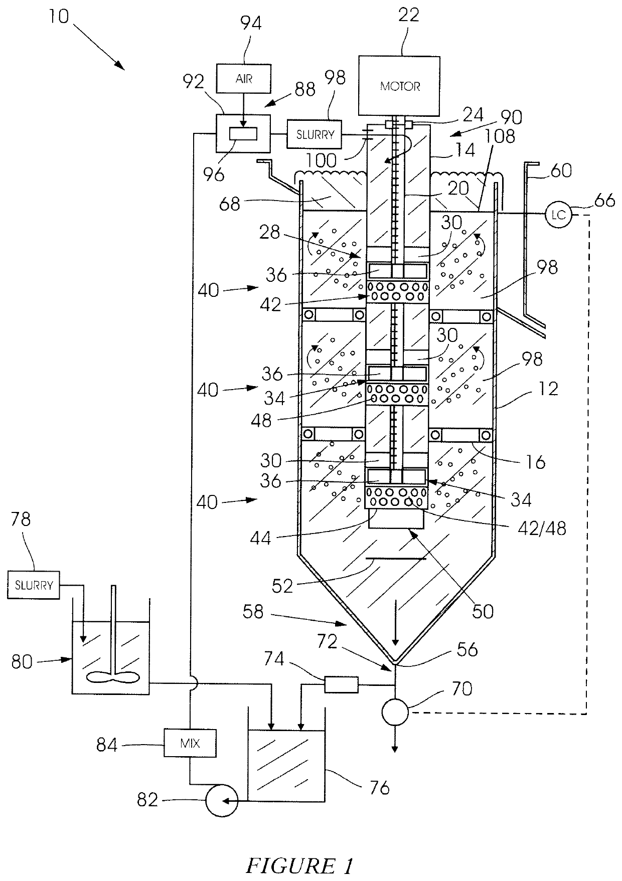
[0038]FIG. 1 of the accompanying drawings illustrates from one side and in cross section a froth flotation apparatus 10 which comprises a pneumo-mechanical cell, according to the invention.

[0039]The apparatus 10 includes a tank 12 which is of any suitable shape but which, conveniently, is circular cylindrical. An elongate, tubular, circular cylindrical downcomer or contactor 14 is centrally positioned inside the tank and extends vertically downwardly inside the tank. The contactor 14 in the embodiment is fixed to a wall of the tank and is supported by means of a plurality of spaced apart supports 16. The invention is, however not limited in this respect.

[0040]An elongate shaft 20 extends from an overhead electrical drive motor 22 (or a connected pulley) through a seal 24 at an upper end of the contactor 14 vertically down inside the contactor 14. The shaft 20, which is suitably supported, extends through a plurality of stators 28 which are located at spaced apart intervals along the...


PUM


Abstract

A froth flotation apparatus including a tank defining an interior, for holding a slurry, an aerator for aerating a mineral feed stream entering the interior and a system for feeding the aerated mineral stream into a contactor located in the tank.

Description

BACKGROUND OF THE INVENTION[0001]This invention relates to an apparatus which makes use of froth flotation techniques to recover valuable minerals from ore.[0002]In a froth flotation process a finely ground ore is pulped and conditioned with chemical reagents to promote the attachment of valuable mineral particles to air bubbles that are dispersed in a slurry. The contacting of the conditioned slurry with air can be done in different ways for example mechanically, using rotor / stator assemblies, or pneumatically, using an aerator. With these techniques the hydrodynamic conditions are, however, such that the air bubbles entrain significant quantities of unwanted gangue material into the froth and the concentrate. In order to reject the unwanted material, the depth of the froth may be increased, or the froth may be washed. Each process, however, leads to a reduced recovery of valuable minerals.[0003]A challenge posed by entrained material is presented in the Platinum Group Mineral (PGM...

Claims


Application Information

Patent Timeline
IPC IPC(8): B03D1/14B03D1/24
CPCB03D1/1456B03D1/247
Inventor ROSS, VICTOR EMUL
Owner MINTEK
Learn More