
Rolling Bearing

a bearing and rolling element technology, applied in the direction of bearings, shafts and bearings, bearings, etc., can solve the problems of bearing failure, limited area moments of inertia that can be achieved in the bearing rings, and premature wear in the region of bearing rings and rolling elements, so as to achieve greater robustness, high axial forces, and improved support

Active Publication Date: 2021-05-27
LIEBHERR COMPONENTS BIBERACH GMBH
View PDF0 Cites 2 Cited by
  • Summary
  • Abstract
  • Description
  • Claims
  • Application Information

AI Technical Summary

Benefits of technology

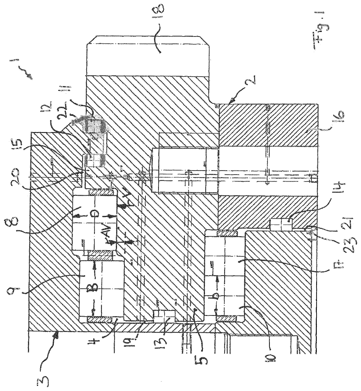
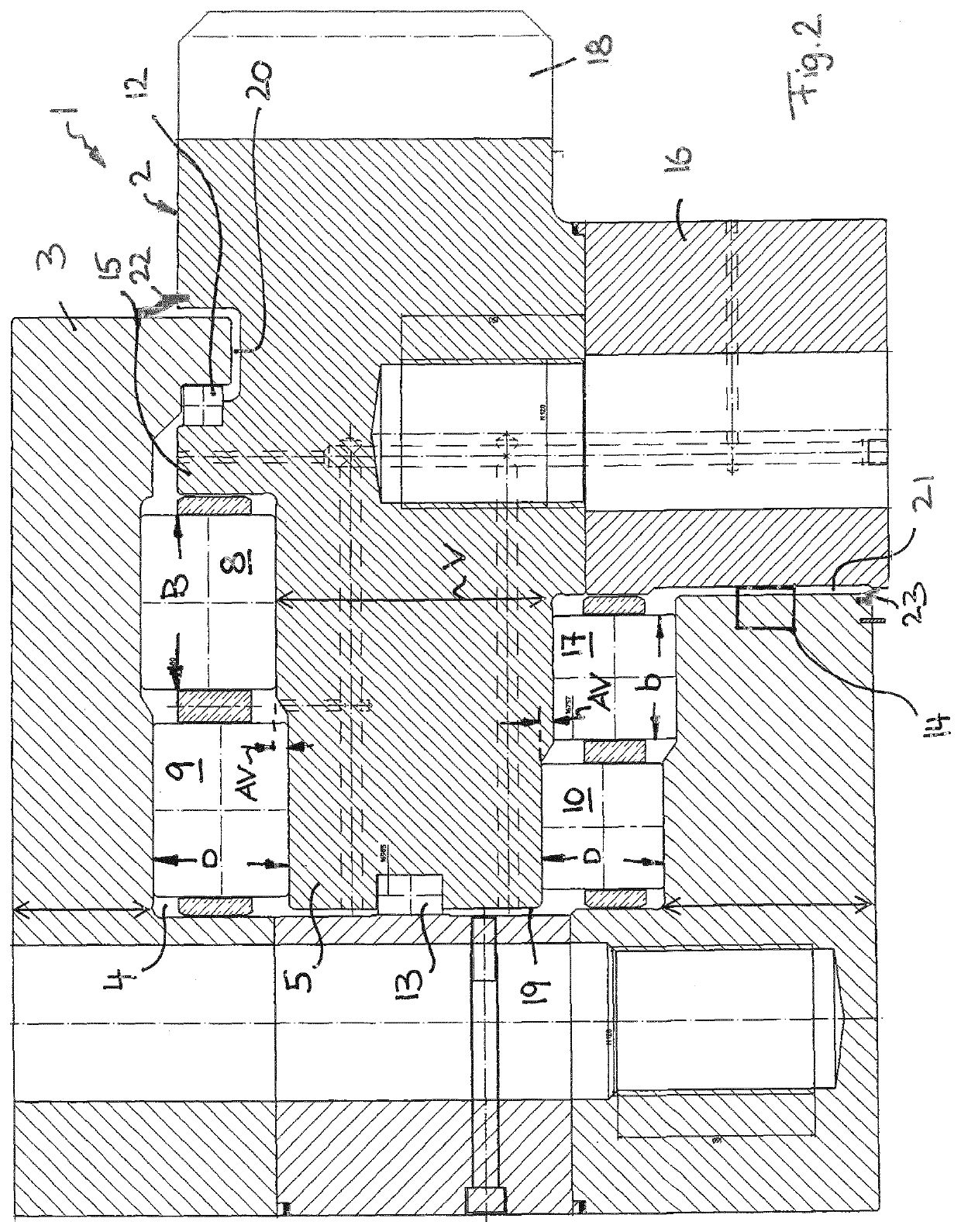
The patent proposes a design for a bearing assembly that supports bearing rings against each other in both the radial and axial directions. By using three or more radial bearings and one axial bearing, the loads are distributed and overloads avoided. The bearing rings can be relatively thin, which reduces weight and material costs. The bearing rings can also be supported against each other by four or more radial bearings, which further increases load distribution and prevents deformation. The axial bearings can be arranged on separate raceways to improve support in the event of twisting or inclination. The width of the axial bearings can be smaller, and the raceways can be narrower, which makes it easier to adapt to deformations and improve load distribution. Overall, the design allows for a thinner and lighter bearing assembly with improved load distribution and reduced costs.

Problems solved by technology

In large ring bearings for special purposes, significant bending moments and tilting forces sometimes act upon the bearing rings, and this can lead to deformation and an angular offset to the bearing rings relative to one another, and so premature wear occurs in the region of the bearing rings and rolling elements.
Due to a lack of space, the bearing rings of an open-center large rolling bearing such as this cannot be manufactured in any desired size, especially in the radial direction, and so the area moments of inertia that can be achieved in the bearing rings are limited.
At the same time, radial deformations can lead to bearing failure.
However, an enlargement of the cross-sections in the scraper and scraper root region leads to a significant increase in weight as well as costs.
On the other hand, such very large bearings are particularly sensitive to even small deformations of the bearing rings and inclination of the rolling element raceways.
However, such wide cylindrical roller bearings react particularly critically to tilting or inclinations of the raceways in relation to one another, since only a very small proportion of the cylindrical rollers are actually supported.

Method used


Image

  • Rolling Bearing
  • Rolling Bearing

Examples


Embodiment Construction

[0046]To facilitate an understanding of the principles and features of the various embodiments of the invention, various illustrative embodiments are explained below. Although exemplary embodiments of the invention are explained in detail, it is to be understood that other embodiments are contemplated. Accordingly, it is not intended that the invention is limited in its scope to the details of construction and arrangement of components set forth in the following description or illustrated in the drawings. The invention is capable of other embodiments and of being practiced or carried out in various ways. Also, in describing the exemplary embodiments, specific terminology will be resorted to for the sake of clarity.

[0047]It must also be noted that, as used in the specification and the appended claims, the singular forms “a,”“an” and “the” include plural references unless the context clearly dictates otherwise. For example, reference to a component is intended also to include composit...


PUM


Abstract

An open-centered large rolling bearing having two concentric bearing rings, which are supported against one another in the axial direction of the rolling bearing by means of at least two axial bearings, which are arranged on opposite end faces of a bearing ring. In the radial direction, the bearing rings are supported against one another by at least three radial bearings, which are arranged on inner and outer circumferential sides of a bearing ring.

Description

CROSS-REFERENCE TO RELATED APPLICATIONS[0001]This application is a National Stage of International Application No. PCT / EP2019 / 063476 filed 24 May 2019, which claims benefit under 35 USC §365 of DE Application No. 20 2018 103 079.5 filed 1 Jun. 2018, each of which is incorporated herein by reference in its entirety as if set forth herein.STATEMENT REGARDING FEDERALLY SPONSORED RESEARCH OR DEVELOPMENT[0002]Not ApplicableTHE NAMES OF THE PARTIES TO A JOINT RESEARCH AGREEMENT[0003]Not ApplicableSEQUENCE LISTING[0004]Not ApplicableSTATEMENT REGARDING PRIOR DISCLOSURES BY THE INVENTOR OR A JOINT INVENTOR[0005]Not ApplicableBACKGROUND OF THE DISCLOSURE1. Field of the Invention[0006]The present invention relates to a rolling bearing, more particularly an open-centered large rolling bearing, having two concentric bearing rings, rotatably relative to one another, which are supported against one another in the axial direction of the rolling bearing by means of at least two axial bearings, whic...

Claims


Application Information

Patent Timeline
Patent Type & Authority Applications(United States)
IPC IPC(8): F16C19/54F16C19/56F16C17/04
CPCF16C19/545F16C19/56F16C2326/30F16C2300/14F16C17/04F16C19/505
Inventor ALTMAYER, THOMASRUF, MARKUSPALMER, ANDREASZELL, ROBERT
Owner LIEBHERR COMPONENTS BIBERACH GMBH
Learn More