
Dental Impression Tray

a technology for dental impressions and trays, applied in dentistry, dental prosthetics, medical science, etc., can solve the problems of inaccurate impressions, tray is difficult to use without harming the patient, and the section is detachable in the middle of the procedur

Inactive Publication Date: 2021-05-27
SOLVING DIGITAL DENTAL INC
View PDF0 Cites 4 Cited by
  • Summary
  • Abstract
  • Description
  • Claims
  • Application Information

AI Technical Summary

Benefits of technology

The dental impression tray is designed to hold dental impression material and is used to take impressions of a patient's teeth. The tray has a U-shaped base with a removable impression table and inner and outer walls that form a bite channel. The table has several knock-out panels that can be easily removed to create an opening. This allows for easy access to the dental material and makes the tray more convenient and user-friendly during dental impression procedures.

Problems solved by technology

When placing dental implants there is the further complication that when making the impression a coping or positioning post is generally placed into the dental implant in order to delineate the location of the implant relative to the neighbouring teeth and relative to the jaw itself.
There are a number of dental impression trays which have been patented, however which do not address the present issue, namely the projection of the coping through the bottom of the base of the dental impression tray for taking impressions which are used for placement for dental implants.
The difficulty with this dental impression tray is the possibility of inadvertent detachment of sections during the taking of an impression.
Another difficulty with this design is the large size of the removable panels which will result in reduction in the structural rigidity of the impression tray causing inaccurate impressions to be taken.
Furthermore, once the sections are removed a large number of sharp edges are exposed which could easily cut or damage the gums of the patient thereby making this tray somewhat difficult to use without harming the patient.
Additionally, by breaking the side creases 25, one is introducing very sharp edges into the mouth of the patient which again tend to create a safety issue, namely the real potential of cutting into the gums of the patient.

Method used


Image

  • Dental Impression Tray
  • Dental Impression Tray
  • Dental Impression Tray

Examples


Embodiment Construction

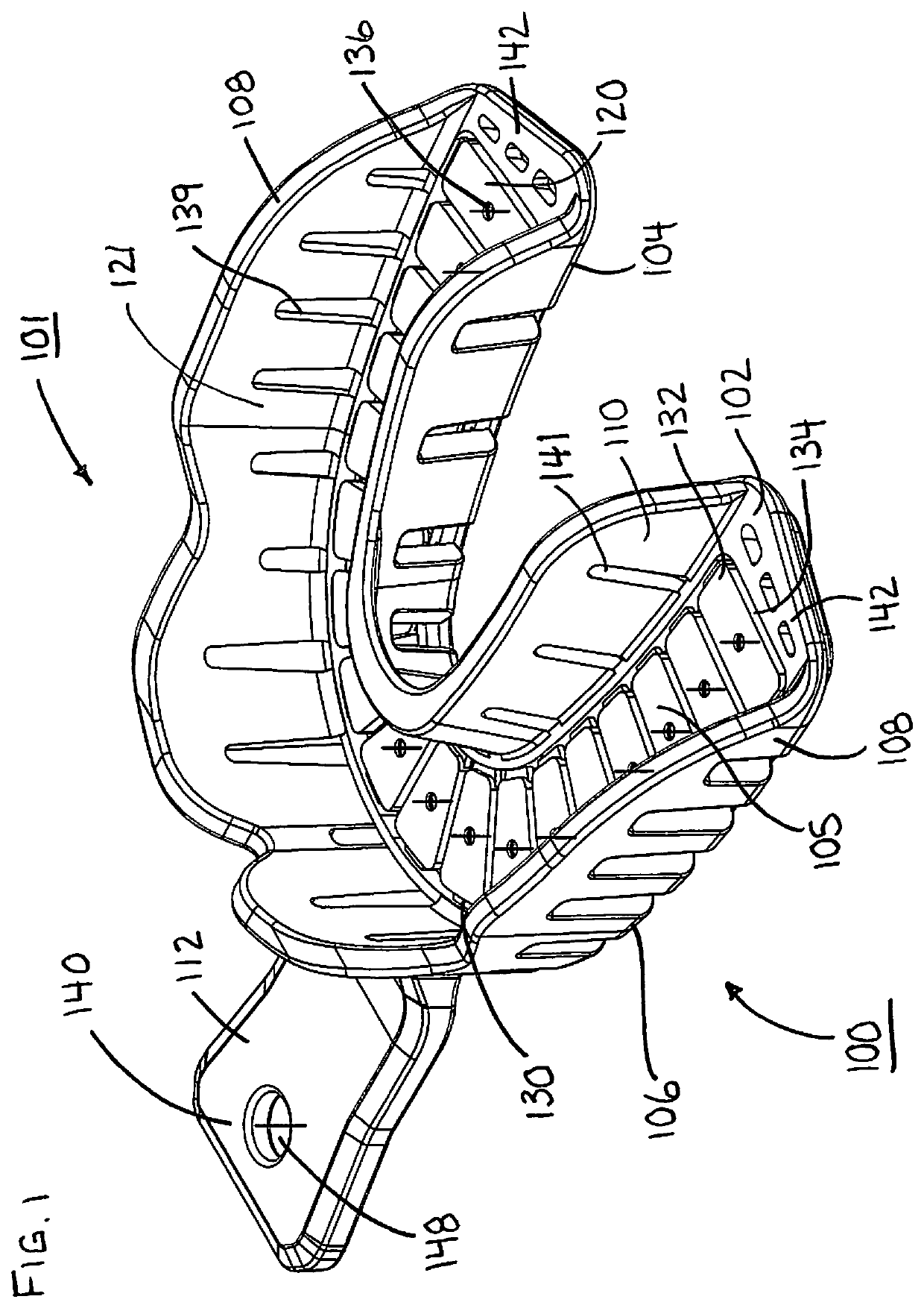
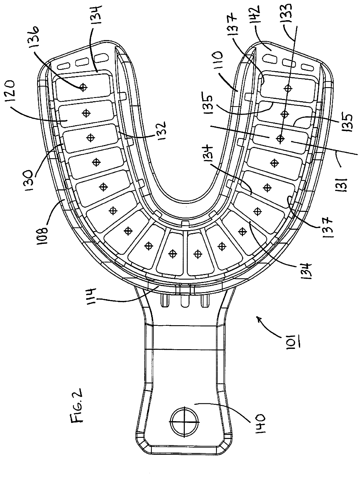
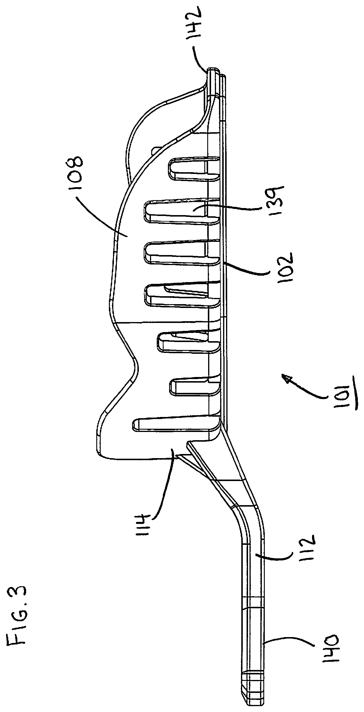
[0024]The present concept A Dental Impression Tray is shown in FIGS. 1 through 10 and more particularly a lower impression tray 101 is shown in FIGS. 1 through 5 and an upper impression tray 103 is shown in FIGS. 6 through 10. The lower impression tray 101 is generally used for taking impressions of the lower jaw whereas the upper impression tray 103 is generally used for taking impressions of the upper jaw. Lower impression tray 101 and upper impression tray 103 are substantially the same except for modifications to the inner wall 210 which includes the addition of a palate guard 209.

[0025]Dental impression tray 100 includes a U shaped base 102, which includes a planar impression table 105, an outer wall 108 and an inner wall 110, wherein the impression table 105 extends between the inner wall 110 along an inner periphery 104 and the outer wall 108 along an outer periphery 106, wherein the inner 110 and outer 108 walls extend upwardly from the base 102.

[0026]Impression table 105 to...


PUM


Abstract

A dental impression tray includes; a U shaped base, which includes a U shaped planar impression table, an outer wall and an inner wall, wherein the impression table extends between the inner wall along an inner periphery and the outer wall along an outer periphery, wherein the inner and outer walls extend upwardly from the base. The impression table together with the inner and outer walls thereby define a U shaped bite channel configured for receiving therein impression material and a set of teeth, thereby operably taking impressions of the teeth. The impression table includes numerous planar knock-out panels arranged in side by side fashion along the center line, the knock-out panels are configured to be selectively removed from the impression table thereby selectively providing an opening through the impression table. Each knock out panel is separated from the adjacent knock out panel by a panel gap at an open side wherein the gap extends transversely to the center line and between the inner and outer wall.

Description

[0001]This application claims priority from U.S. provisional application No. 62 / 941,000 filed Nov. 27, 2019 under the title “A Dental Impression Tray” by inventor Jonathan Mahn.FIELD OF THE INVENTION[0002]The present concept relates generally to dental impression trays and more particularly relates to dental impression trays for dental implants.BACKGROUND OF THE INVENTION[0003]Dental impression trays are used to hold dental impression material which is then placed into the jaw or mouth of the patient in order that an impression of the teeth and or the voids that are present within the upper or lower set of teeth can be reproduced in the form of a negative impression. Normally the impression material is placed in the tray before it is placed either into the upper or lower jaw over top of the teeth and gums. The dental impression trays are normally shaped and or fitted over the teeth and gums in a jaw to fit over the teeth and gums in a comfortable manner. It is often necessary to hav...

Claims


Application Information

Patent Timeline
Patent Type & Authority Applications(United States)
IPC IPC(8): A61C9/00
CPCA61C9/0006
Inventor MAHN, JONATHAN
Owner SOLVING DIGITAL DENTAL INC
Learn More