
Methods, apparatuses, and devices for providing traction to a tracked vehicle

Pending Publication Date: 2021-05-20
BLANCHARD JOHN
View PDF12 Cites 3 Cited by
  • Summary
  • Abstract
  • Description
  • Claims
  • Application Information

AI Technical Summary

Benefits of technology

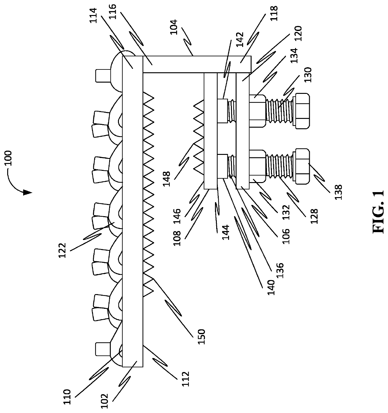
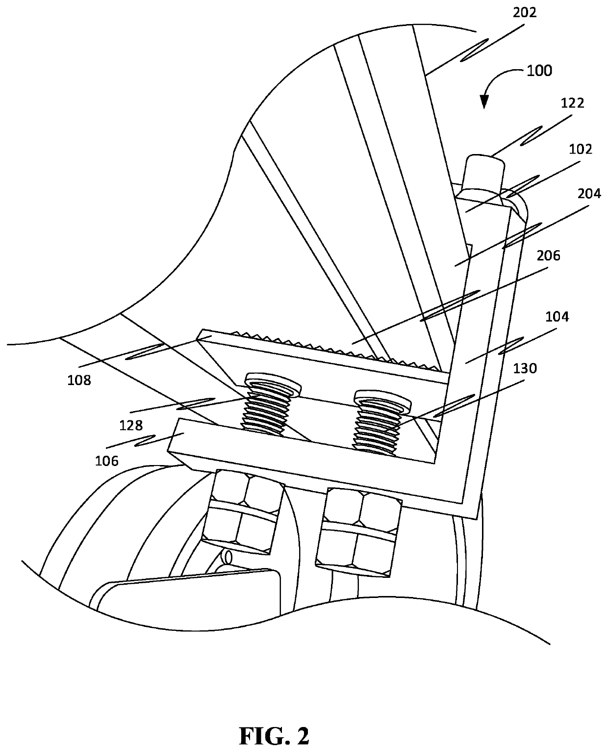
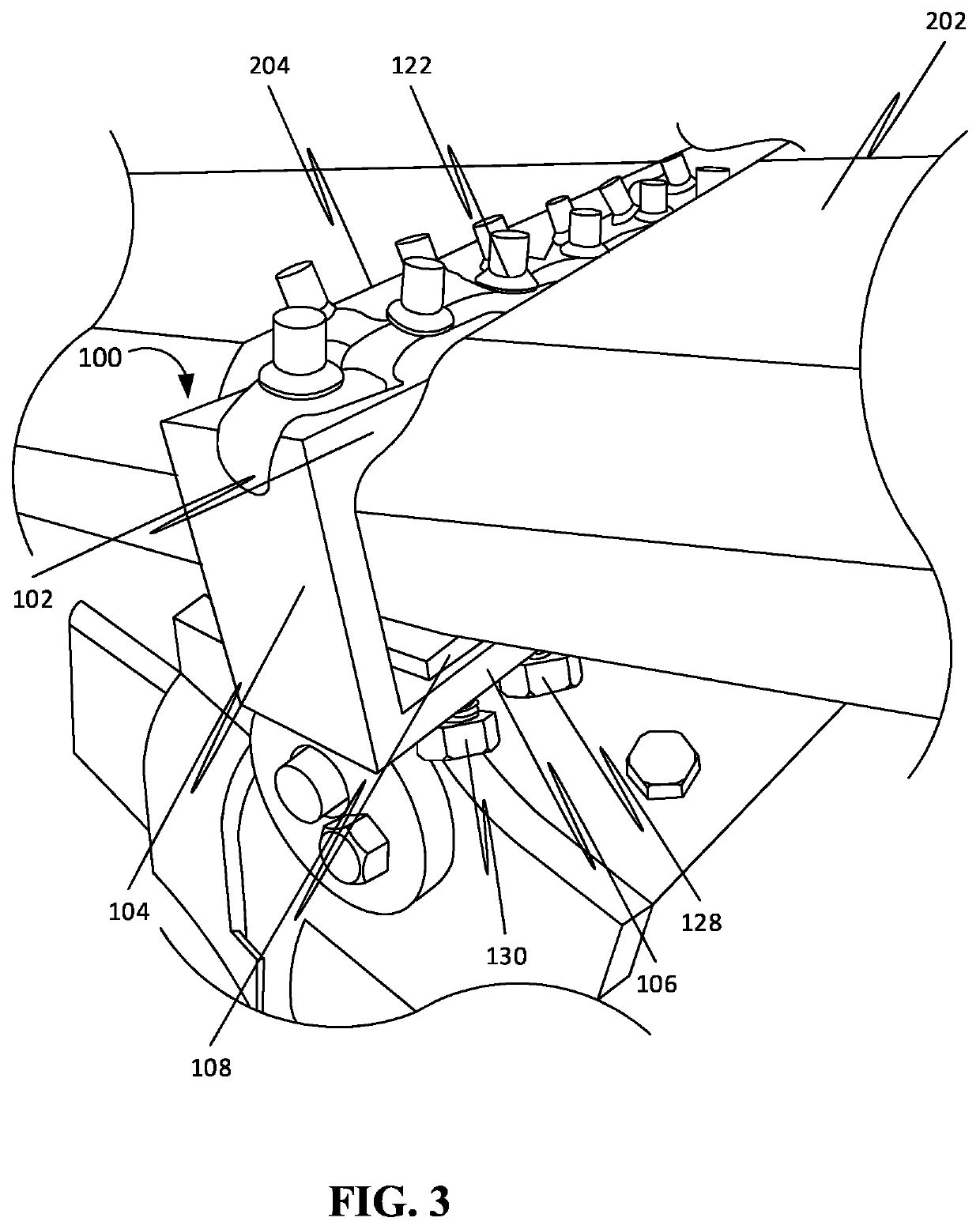
The patent describes a traction device for a tracked vehicle that includes a grouser bar, down plate, bottom plate, pressure plate, and bolt. The grouser bar has a traction element on its top surface for providing traction to the track. The down plate is attached to the grouser bar and extends over the side surface of the track. The bottom plate is attached to the down plate and presses against the track in a position to provide traction. The pressure plate is movable between different positions to either secure or release the track. The bolt is threadedly coupled to the nut and can be moved to change the position of the pressure plate. The technical effect of this invention is to provide a traction device that can securely attach to the track and provide traction for the vehicle.

Problems solved by technology

Further, a first end of the at least one bolt interfaces with an inferior surface of the pressure plate.

Method used


Image

  • Methods, apparatuses, and devices for providing traction to a tracked vehicle
  • Methods, apparatuses, and devices for providing traction to a tracked vehicle
  • Methods, apparatuses, and devices for providing traction to a tracked vehicle

Examples


Embodiment Construction

[0029]As a preliminary matter, it will readily be understood by one having ordinary skill in the relevant art that the present disclosure has broad utility and application. As should be understood, any embodiment may incorporate only one or a plurality of the above-disclosed aspects of the disclosure and may further incorporate only one or a plurality of the above-disclosed features. Furthermore, any embodiment discussed and identified as being “preferred” is considered to be part of a best mode contemplated for carrying out the embodiments of the present disclosure. Other embodiments also may be discussed for additional illustrative purposes in providing a full and enabling disclosure. Moreover, many embodiments, such as adaptations, variations, modifications, and equivalent arrangements, will be implicitly disclosed by the embodiments described herein and fall within the scope of the present disclosure.

[0030]Accordingly, while embodiments are described herein in detail in relation...


PUM


Abstract

Disclosed herein is a traction device for providing traction to a tracked vehicle, in accordance with some embodiments. Accordingly, the traction device comprises a grouser bar, a down plate, a bottom plate, a pressure plate, and a bolt. Further, the grouser bar comprises a traction element comprised in a top surface of the grouser bar. Further, the traction element is configured to interface with a surface for providing traction for the track on the surface. Further, the down plate is attached to the grouser bar. Further, the bottom plate is attached to the down plate. Further, the pressure plate is movably disposed between the grouser bar and the bottom plate. Further, the bolt is movably coupled with the pressure plate. Further, the bolt is configured for moving the pressure plate between positions in relation to the bottom plate based on an action receivable on a second end of the bolt.

Description

[0001]The current application claims a priority to the U.S. Provisional Patent application Ser. No. 62 / 935,786 filed on Nov. 15, 2019.FIELD OF THE INVENTION[0002]Generally, the present disclosure relates to the field of wheel substitutes for land vehicles. More specifically, the present disclosure relates to methods, apparatuses, and devices for providing traction to a tracked vehicle.BACKGROUND OF THE INVENTION[0003]Weather events such as rain, snow, and ice dramatically affect the stopping distance of a vehicle. The driver's capability to complete a smooth and safe stop is severely limited due to reduced track plate traction. In order to stop safely, the vehicle's continuous rubber tracks must maintain traction by maintaining a contact with the road surface while rolling. When handling slippery winter roads, the keys to safety are slower speeds, and gentler stops and turns. Currently, there are a number of attempts for solutions to increase the traction of rubber-tracked construct...

Claims


Application Information

Patent Timeline
IPC IPC(8): B62D55/28
CPCB62D55/283B62D55/27
Inventor BLANCHARD, JOHN
Owner BLANCHARD JOHN
Learn More