
Methods and systems for reducing rotor acoustics of an aircraft

a technology of rotors and aircraft, applied in the direction of vertical landing/take-off aircraft, efficient propulsion technologies, transportation and packaging, etc., can solve the problems of affecting the flight safety of aircraft, etc., to achieve the effect of reducing the rotor acoustics of the aircra

Pending Publication Date: 2021-05-13
BETA AIR LLC
View PDF3 Cites 8 Cited by
  • Summary
  • Abstract
  • Description
  • Claims
  • Application Information

AI Technical Summary

Benefits of technology

This patent describes a system and method for reducing the noise of rotors on an aircraft. The system includes a plurality of rotors and a controller that can initiate rotation of the rotors in a coordinated manner to reduce noise. An alignment module detects the rotation of the propulsor and a rotational control module initiates the rotation of the rotors at different times to create a phase difference. The method also involves aligning the orientations of the rotors based on wind information. Overall, this system and method can improve the efficiency and comfort of flight.

Problems solved by technology

Historically, critical components of aircrafts and other machinery configured for flight have been susceptible to acoustic effects caused by harmonics associated with the rotational frequency of the critical components.
Acoustic effects can be transmitted from the critical component to the body of the aircraft and / or other machinery configured for flight, resulting in periodic and / or random oscillation.
The oscillations can result in fatigue to the pilot, crew, and / or passengers, damage to critical components of the aircraft and other machinery configured for flight, resulting in improper or limited functionality, and / or damage to the payload.

Method used


Image

  • Methods and systems for reducing rotor acoustics of an aircraft
  • Methods and systems for reducing rotor acoustics of an aircraft
  • Methods and systems for reducing rotor acoustics of an aircraft

Examples


Embodiment Construction

[0018]In the following description, for the purposes of explanation, numerous specific details are set forth in order to provide a thorough understanding of the present invention. It will be apparent, however, that the present invention may be practiced without these specific details. As used herein, the word “exemplary” or “illustrative” means “serving as an example, instance, or illustration.” Any implementation described herein as “exemplary” or “illustrative” is not necessarily to be construed as preferred or advantageous over other implementations. All of the implementations described below are exemplary implementations provided to enable persons skilled in the art to make or use the embodiments of the disclosure and are not intended to limit the scope of the disclosure, which is defined by the claims. For purposes of description herein, the terms “upper”, “lower”, “left”, “rear”, “right”, “front”, “vertical”, “horizontal”, and derivatives thereof shall relate to the invention ...


PUM


Abstract

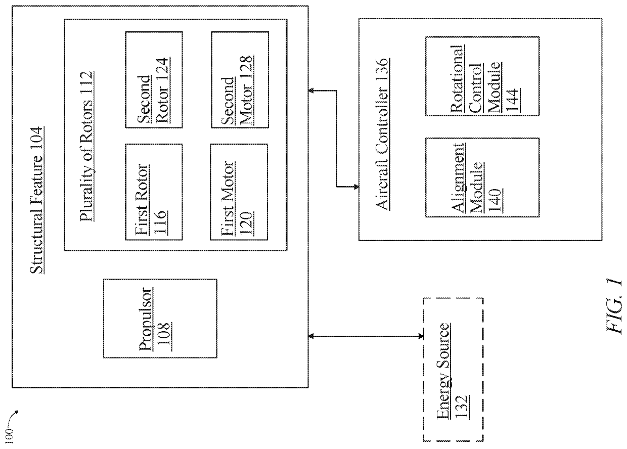
A system for reducing rotor acoustics of an aircraft. The system includes a structural feature of an aircraft and a propulsor configured for fixed-wing flight mounted on the structural feature. The system further includes a plurality of rotors mounted on the structural feature. The plurality of rotors are configured to include a first rotor, a first motor mechanically coupled to the first rotor, a second rotor, and a second motor mechanically coupled to the second rotor. The system further includes an aircraft controller communicating with the first motor, second motor, and the propulsor. The system includes an alignment module configured to place the second rotor in alignment with the first rotor. The system further includes a rotational control module configured to initiate rotation of the plurality of rotors. Initiating rotation of the plurality of rotors further includes initiating rotation of the first rotor and the second rotor.

Description

FIELD OF THE INVENTION[0001]The present invention generally relates to the field of rotor systems for an aircraft. In particular, the present invention is directed to methods and systems for reducing rotor acoustics of an aircraft.BACKGROUND[0002]Historically, critical components of aircrafts and other machinery configured for flight have been susceptible to acoustic effects caused by harmonics associated with the rotational frequency of the critical components. Acoustic effects can be transmitted from the critical component to the body of the aircraft and / or other machinery configured for flight, resulting in periodic and / or random oscillation. The oscillations can result in fatigue to the pilot, crew, and / or passengers, damage to critical components of the aircraft and other machinery configured for flight, resulting in improper or limited functionality, and / or damage to the payload. The need for a means of correcting acoustic effects created and transmitted by critical components...

Claims


Application Information

Patent Timeline
Patent Type & Authority Applications(United States)
IPC IPC(8): B64C27/00B64D27/24B64C29/00B64D31/14B64F5/60B64D31/06B64C27/10
CPCB64C27/001B64D27/24B64C29/0025B64C2220/00B64F5/60B64D31/06B64C27/10B64D31/14B64D31/12B64D27/02Y02T50/60
Inventor CLARK, KYLEFERRIER, LOCHIE
Owner BETA AIR LLC
Learn More