
Multi-element antenna conformed to a conical surface

Active Publication Date: 2021-04-22
CUBIC CORPORATION
View PDF0 Cites 2 Cited by
  • Summary
  • Abstract
  • Description
  • Claims
  • Application Information

AI Technical Summary

Benefits of technology

The present invention provides an RF seeker antenna for use in low-cost smart munitions (projectiles) that can withstand harsh environmental conditions. The seeker antenna can be adapted to fit different projectile platforms and can operate at various frequencies of interest. The technical effect is that it enables efficient and reliable targeting of targets even in challenging conditions.

Problems solved by technology

The top surface of the waveguides may be leaky to quasi-guided radio frequencies and may be exposed to the operating environment.

Method used


Image

  • Multi-element antenna conformed to a conical surface
  • Multi-element antenna conformed to a conical surface
  • Multi-element antenna conformed to a conical surface

Examples


Embodiment Construction

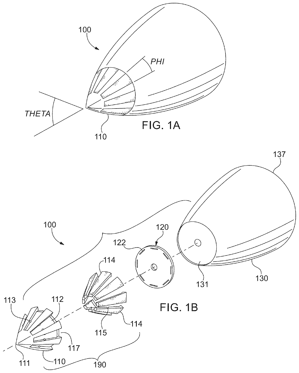
[0023]Referring now to the figures, wherein like elements are numbered alike throughout, an exemplary antenna 190 integrated into a compact conical-, ogive-, Von Karman-, etc. shaped nosecone assembly 100 is illustrated, FIGS. 1A, 1B. The nosecone assembly 100 may include a nosecone 110 and adjoining nosecone body 130 with forward and aft ends 131, 137, respectively, which body 130 may house electronics and other components not related to the antenna 190. The assembly 100 may include a nosecone 110 which houses the radiating antenna elements, namely leaky dielectric-loaded waveguides 114. The leaky dielectric-loaded waveguides 114 may be seated in corresponding recesses 112 provided in the nosecone 110. To assist in retaining the dielectric-loaded waveguides 114 in the nosecone 110, tabs 113 may be provided in the recesses 112 for mating to corresponding detents 115 in the waveguides 114, FIGS. 1B, 10-12B. In addition, the tabs 113, as well as nubs, baffles, apertures, perforations,...


PUM


Abstract

Antenna integrated into a compact conical nosecone.

Description

[0001]This application claims the benefit of priority of U.S. Provisional Application No. 62 / 897,532, filed on Sep. 9, 2019, the entire contents of which application(s) are incorporated herein by reference.GOVERNMENT LICENSE RIGHTS[0002]This invention was made with government support under Contract No. W31P4Q-17-C-0051 awarded by identify the United States Army. The government has certain rights in the invention.FIELD OF THE INVENTION[0003]The present invention relates generally to multi-element antennas and more particularly but not exclusively to multi-element antennas conformed to a conical surface and associated feed structures.SUMMARY OF THE INVENTION[0004]In one of its aspects the present invention may be useful in weapon systems by providing an RF seeker antenna usable in low-cost smart munitions fired as artillery (projectiles) with the seeker antenna capable of surviving harsh environmental conditions. In one exemplary configuration, a 40-mm projectile is shown notionally, ...

Claims


Application Information

Patent Timeline
IPC IPC(8): H01Q1/28H01Q13/10
CPCH01Q1/28H01Q13/10H01Q1/281H01Q13/06H01Q21/0056H01Q11/105H01Q1/422
Inventor JORDAN, JARED WILLIAMSSMITH, TIMOTHY AMISPINERO, FREDDYKERRIGAN, BRIAN MICHAEL
Owner CUBIC CORPORATION
Learn More