Pond filter and method for operating the pond filter

Active Publication Date: 2021-04-08
EASYFIRM APS
View PDF0 Cites 3 Cited by
  • Summary
  • Abstract
  • Description
  • Claims
  • Application Information

AI Technical Summary

Benefits of technology

The present invention provides an improved pond filter unit and a method for operating it that is effective in purifying and recycling pond water with a high load of particulate matter, nutrients, and organic carbon, and reduces the risk of clogging. The filter unit includes temperature sensors that measure the water temperature in the pond or in the filter unit and adjust the frequency of filter cleaning and UV-lamp, and also control the feeding rate of an automatic feeding device. The invention allows for better maintenance of the pond water quality and reduces the risk of algae production.

Problems solved by technology

Membrane filters and sand filters are highly unsuitable in cleaning water from fish ponds because the water is medium to heavily loaded with particulates (and nutrients, organic carbon) and will clog very quickly.
If the filter does not perform in an optimal manner, e.g. because of clogging of the filter material due to this may lead to reduced performance of the pond filter unit leading to insufficient purification of the water in the pond and thus cause increased growth of algae, death or diseases in the fish stock present in the pond etc.
This risk is eliminated when using specially designed plugs, because it is not be possible to connect other equipment that is used around the fish pond, e.g. an electrical lawn mower, to the plugs.
If the biofilter is cleaned with too low frequency, there is a risk that a certain part of the microorganisms present in the biofilm dies and degrades, thus resulting eutrophication of the fish pond.

Method used


Image

  • Pond filter and method for operating the pond filter
  • Pond filter and method for operating the pond filter
  • Pond filter and method for operating the pond filter

Examples


Embodiment Construction

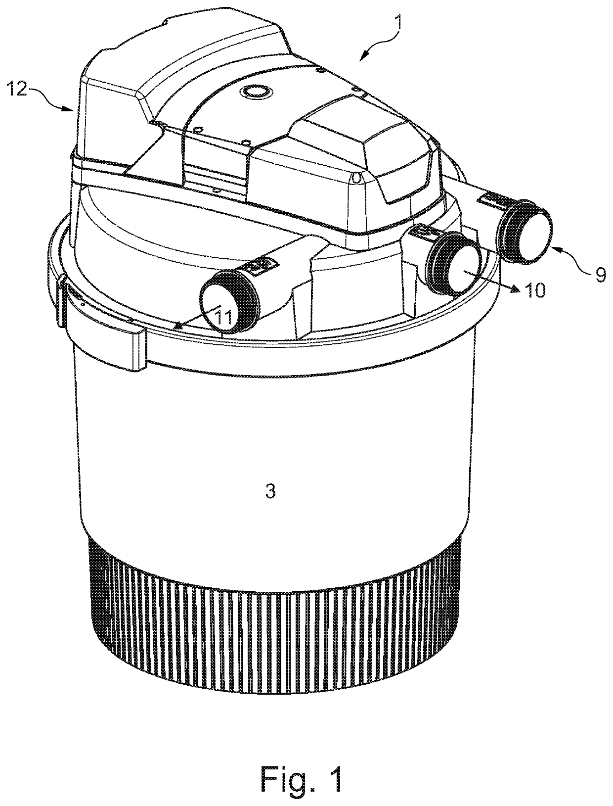
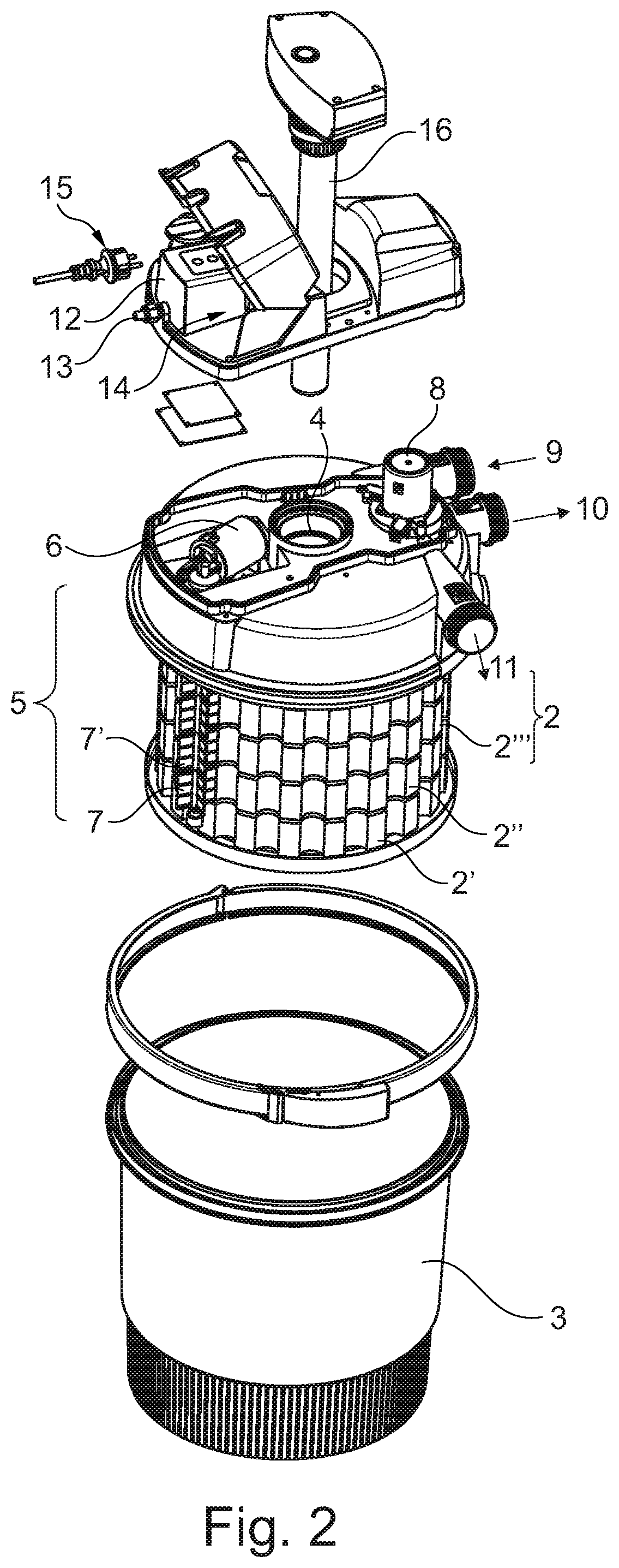
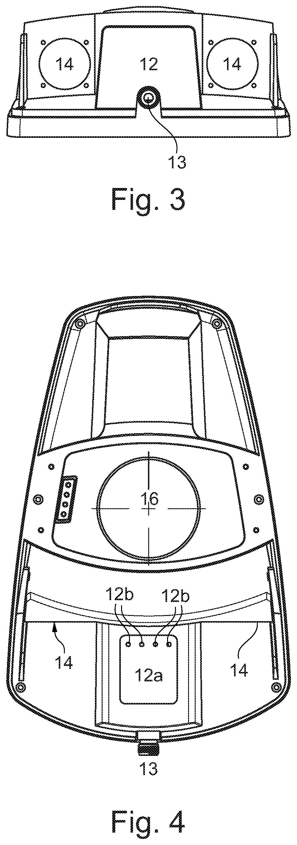
[0096]FIGS. 1-4 show a pond filter unit 1 according to embodiments of the present invention.

[0097]The pond filter 1 comprises a filter body 1. The filter body 2 in the pond filter unit comprises at least one or more blocks 2’, 2″, 2′″ of flexible filter material, such as polymeric open pored foam or a flexible block of fibrous filter material that are arranged in a vessel 3. The one or more filter blocks 2′, 2″, 2′″ comprises a central hole which is arranged on a central tube 4 that defines an outlet. In this way the one or more filter blocks 2, 2′, 2′″ are arranged to be rotatable in the vessel 3.

[0098]The motorized cleaning unit 5 comprises a rotatable longitudinal rod 7 arranged in connection with the periphery of the filter material 2. The rotatable rod 7 presses against the outer surface of the one or more blocks of filter material 2. The rotatable rod has a profiled surface that causes a mechanical action against the outer surface of the filter blocks when the rod 5′ is rotate...


PUM

PropertyMeasurementUnit
Flow rateaaaaaaaaaa
Flexibilityaaaaaaaaaa
Currentaaaaaaaaaa

Abstract

A pond filter unit and a method for operating a pond filter unit is provided. A control unit controls the operation of the pond filter unit, including the cleaning cycle of the filter. The pond filter unit further includes one or more plugs for connecting one or more auxiliary devices, such as a separate pump, one or more additional pond filter units, illumination means / lamps, air pumps, and / or feed automats. The control unit of the pond filter further controls the one or more auxiliary devices connected to the plugs, such as pumps, air pumps, automatic feeding devices based on input settings for each of the one or more auxiliary devices. The control unit further controls the cleaning cycle for cleaning of the filter in the vessel.

Description

CROSS-REFERENCE TO RELATED APPLICATIONS[0001]This application claims priority to PCT Application No. PCT / EP2018 / 061074, having a filing date of May 1, 2018, which is based on EP Application No. 17169016.7, having a filing date of May 2, 2017, the entire contents both of which are hereby incorporated by reference.FIELD OF TECHNOLOGY[0002]The following relates to a pond filter unit for pumping, circulating and purifying water in ponds, fountains or similar aquatic applications, the pond filter unit comprising a filter unit contained in a vessel, a pump and at least one valve for controlling the water flow to and from the filter unit, and where the pond filter further comprises a cleaning arrangement for cleaning the filter material in the pond filter.[0003]In addition, the following relates to a method for operating a pond filter unit according to embodiments of the present invention.BACKGROUND[0004]Presently, pond filter units are used for applications in relation to fish ponds, foun...

Claims


Application Information

Patent Timeline
IPC IPC(8): C02F9/00C02F1/00B01D29/31B01D29/60B01D29/64B01D29/66B01D39/16B01D24/46B01D24/28A01K63/04A01G31/00A01K61/80
CPCC02F9/005C02F1/008B01D29/31B01D29/60B01D29/6476B01D29/668C02F2103/007B01D24/46B01D24/28A01K63/045A01G31/00A01K63/047A01K61/80B01D39/1676A01K63/04C02F1/001C02F1/32C02F2201/326C02F2209/008C02F2209/02C02F2209/03C02F2209/22C02F2209/42C02F2303/16B01D29/33B01D29/606B01D29/66B01D2201/54B01D2201/56Y02W10/37Y02P60/60C02F9/20A01G2031/006B01D2201/16C02F1/325C02F3/103C02F3/109C02F2101/105C02F2101/163C02F2201/005
Inventor FRAUSING, NIELS
Owner EASYFIRM APS
Why Eureka
Try Eureka