Impeller for snowblower and combined snowblower and snowplow
a technology for snowblowers and impellers, which is applied in the field of snowblower impellers, can solve the problem of not being able to combine on all types of vehicles
- Summary
- Abstract
- Description
- Claims
- Application Information
AI Technical Summary
Benefits of technology
Problems solved by technology
Method used
Image

Examples
first embodiment
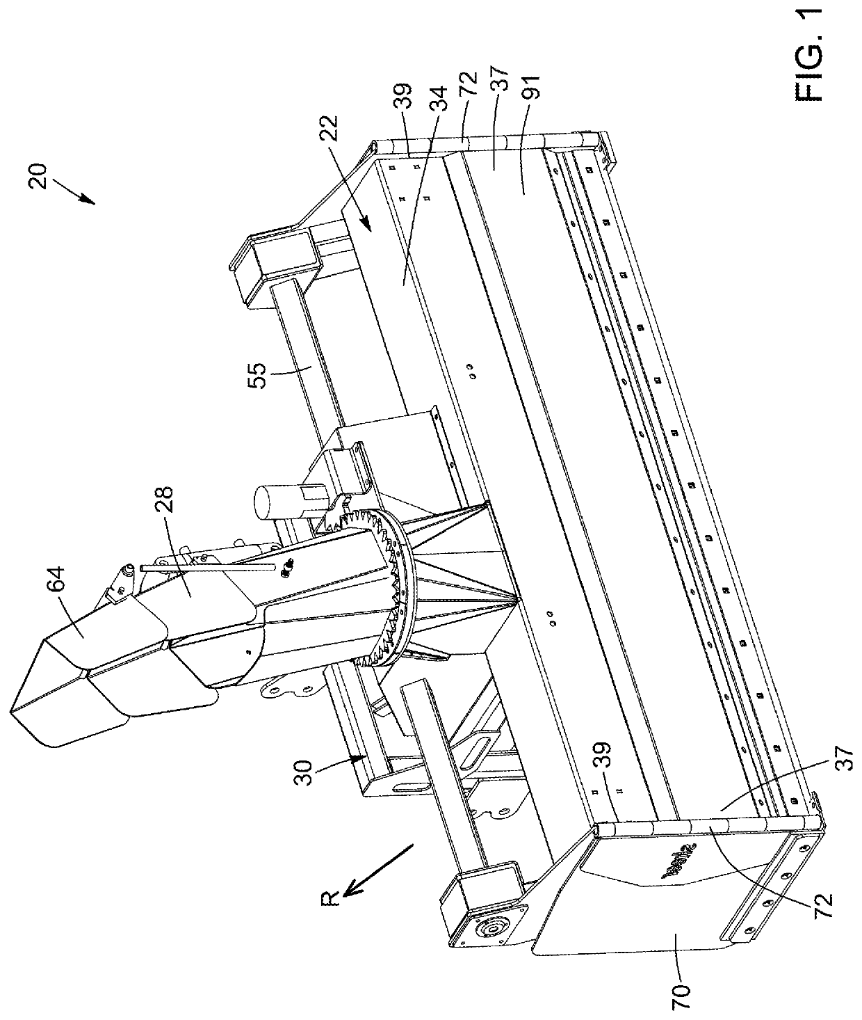
[0068]In the first embodiment shown, in FIGS. 1 to 14, the impeller driving shaft 58 extends parallel to the rotating axles 38—or auger rotating axles 38—of the auger assembly 24 and is spaced apart therefrom. In other words, the at least one rotating axle 38 of the auger assembly 24 and the impeller assembly 26 are not concentric but extend parallel to and spaced apart from one another.
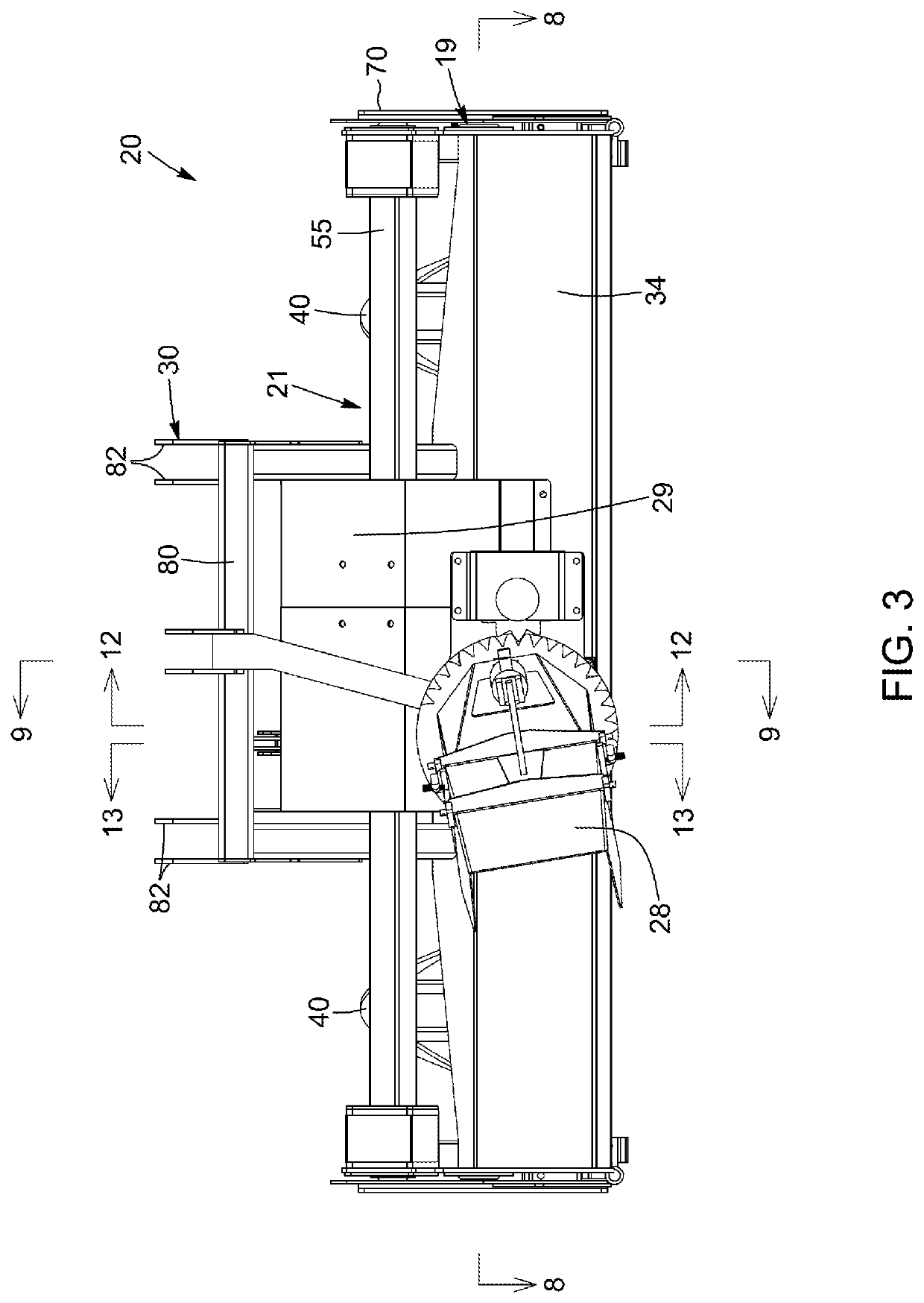
[0069]The transversally extending portion 34 of the snowblower frame 22 comprises an auger-facing side 90 and an opposed snowplowing side 91. As best shown in FIG. 12, the impeller rotation axis X2 extends at least one of above the auger rotation axis X1 and further from the auger-facing side 90 of the transversally extending portion 34 than the auger rotation axis X1, when the snowblower 20 is in use (i.e. when supported on a ground surface). In other words, in the embodiment shown, the impeller rotation axis X2 extends rearwardly with respect to the auger rotation axis X1. In yet other words, the i...
second embodiment
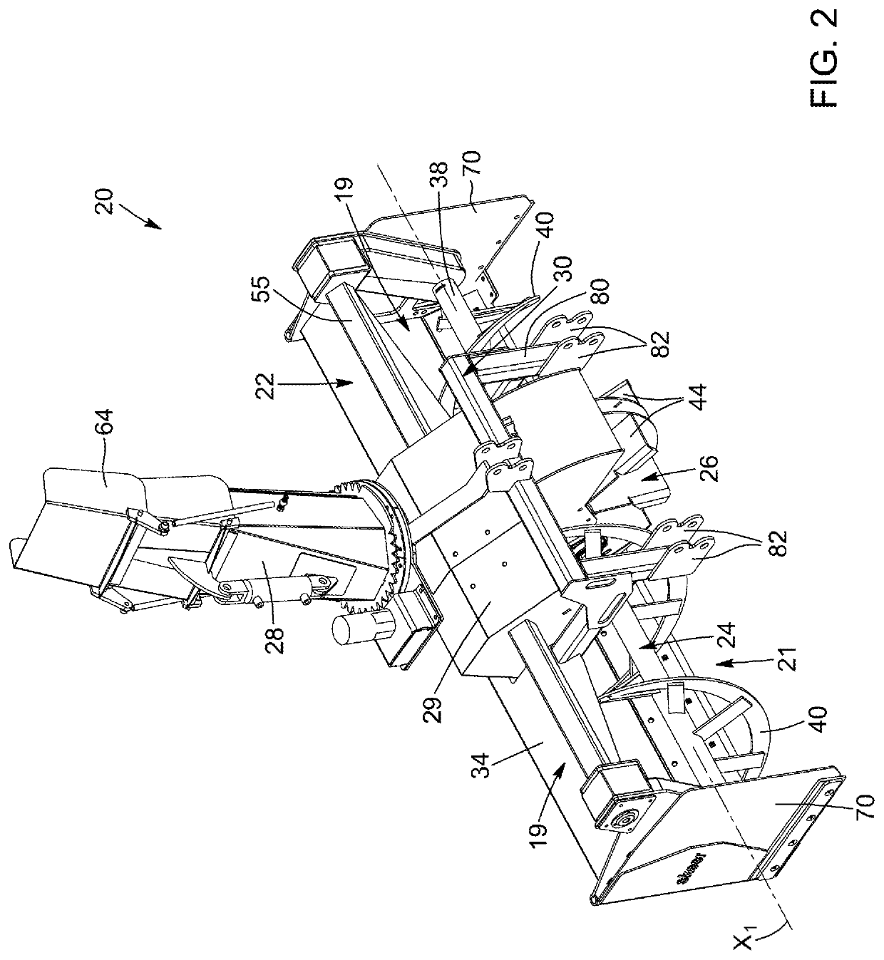
[0071]Since the impeller rotating axle 58 is located at least one of upwardly and rearwardly with respect to the rotating axles 38 of the auger assembly 24, the impeller assembly 26 is characterized by a diameter d2 greater than an auger diameter of a snowblower. Therefore, since the paddles 44 extend at substantially a same height than the helical screw segments 40 of the auger assembly 24 with respect to the ground surface in a lower portion of the snowblower 20, each one of the paddles 44 is longer in comparison with a snowblower wherein the impeller and auger rotating axes would be substantially concentric (as in the second embodiment represented in FIGS. 15 to 20).
[0072]Moreover, due to the relative arrangement of the impeller and auger rotating axes X2, X1, the impeller diameter d2 is greater than or equal to an auger diameter dl of the auger assembly 24, allowing thereby to throw snow at a greater distance and / or to efficiently throw snow directed towards the impeller assembl...
third embodiment
[0112]In this third embodiment, the impeller rotation axis X2 is concentric with the auger rotating axis X1. In the embodiment shown, the impeller assembly 126 comprises an impeller driving shaft 158 with the plurality of paddles 144 being supported thereby and rotating therewith. The impeller driving shaft 158 is mounted to the rotating axle 138, for instance substantially centrally thereof, and is rotatable around the rotating axle 138. For instance, the impeller driving shaft 158 is mounted between the two snow-gathering devices 140 (for instance the helical screw segments 140) of the auger assembly 124. In the embodiment shown, the impeller driving shaft 158 surrounds a central portion of the auger rotating axle 138 extending between the two snow-gathering devices 140. The impeller driving shaft 158 is thus rotatable around the rotating axle 138.
[0113]In the embodiment shown, and similarly to the previously described embodiments, the actuator assembly 149 includes a transmission...
PUM
 Abstract
Description
Claims
Application Information
 - R&D
- Intellectual Property
- Life Sciences
- Materials
- Tech Scout
- Unparalleled Data Quality
- Higher Quality Content
- 60% Fewer Hallucinations
Browse by: Latest US Patents, China's latest patents, Technical Efficacy Thesaurus, Application Domain, Technology Topic, Popular Technical Reports.
© 2025 PatSnap. All rights reserved.Legal|Privacy policy|Modern Slavery Act Transparency Statement|Sitemap|About US| Contact US: help@patsnap.com