Ultrasonic waveguide for improved ultrasonic thermometry

a technology of ultrasonic thermometry and ultrasonic waveguide, which is applied in the direction of heat measurement, instruments, and solids analysis using sonic/ultrasonic/infrasonic waves, can solve problems such as energy loss, and achieve the effects of reducing the number of instrument penetrations, minimizing obstructions, and high sensitivity

Pending Publication Date: 2021-02-25
UT BATTELLE LLC +1
View PDF2 Cites 0 Cited by
  • Summary
  • Abstract
  • Description
  • Claims
  • Application Information

AI Technical Summary

Benefits of technology

[0011]In one embodiment, the ultrasonic waveguide of the present invention employs a series of sensing zones each of which includes periodic structures formed of fused alternating materials to deliver a similar notch-filter response. These materials are selected based on their acoustic impedance values at the nominal operating temperatures as well as their chemical compatibility with the base waveguide material and the material of the other layer, and mechanical and chemical compatibility with the environment. In one approach of making these periodic structures, layers can be formed by introduction of one material and alternating with the waveguide base material. In an alternative approach, the layers may be selected from materials different from the waveguide base material. In one approach, each layer of the fused alternating materials has a thickness of approximately one-quarter wavelength for the material and the geometry at the center design frequency. Alternatively, the thicknesses of layers can be selected to mimic a sinusoidally varying acoustic impedance to eliminate repeated rejections at odd-multiple harmonics. In yet another alternative method, more complex geometric arrangements can be made that use more than two materials to form a periodic structure using forward- and inverse-physics solutions and implementing an optimization method to yield a narrow and more refined rejection.
[0013]In another embodiment, the ultrasonic waveguide of the present invention includes a series of sensing zones each of which employs periodic structures formed by alternating cross-sectional area. This can be achieved by removal of material using various machining methods and tools. The change in cross-sectional area causes change in the one-dimensional acoustic impedance of the waveguide. In one approach, a sharp step-down variation in area is used. Alternatively, more complex geometric shapes can be adopted to improve the rejection performance. The desired band-rejection response can be obtained in several ways. One method uses thicknesses for each layer that equals one-quarter wavelength for the material and the geometry at the center design frequency. This causes reflected waves at each boundary that are out of phase with the incoming wave. The result is full reflection of incoming waveform within a narrow frequency band around the design frequency. If the incoming wave frequency is outside the band, this condition is no longer satisfied, and the waveform is mostly (ideally fully) transmitted. This design approach leads to a repeated notch-filter behavior where the same wave rejection is observed at odd-numbered harmonics of the center frequency. In an alternative approach, the notch filter is created by varying thicknesses that yield a sinusoidally changing acoustic impedance. In this approach, the spurious rejections can be greatly reduced and rejections at odd-number harmonics are virtually eliminated. Alternatively, other geometric arrangements can be employed using forward- and inverse-physics solutions and implementing an optimization method, such as generic algorithms to yield a narrow and more refined rejection.
[0015]The improved ultrasonic waveguide of the present invention possesses the ability to measure temperature at multiple locations with higher sensitivity in high-temperature and potentially harsh applications, such as the a nuclear reactor core, using a single waveguide thereby reducing the number of instrument penetrations and minimizing the obstructions in the fluid flow path. These and other features and advantages of the present invention will become apparent from the following description of the invention, when viewed in accordance with the accompanying drawings and appended claims.

Problems solved by technology

However, as the elastic waves propagate down the waveguide, they lose energy as they pass the sensing zones round trip.

Method used


Image

  • Ultrasonic waveguide for improved ultrasonic thermometry
  • Ultrasonic waveguide for improved ultrasonic thermometry
  • Ultrasonic waveguide for improved ultrasonic thermometry

Examples


Embodiment Construction

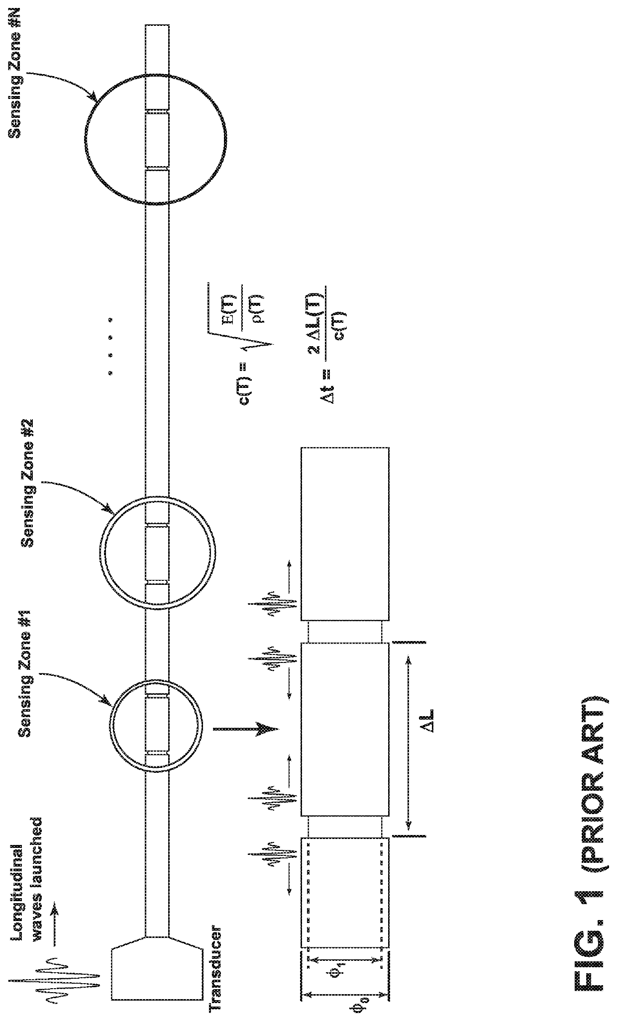
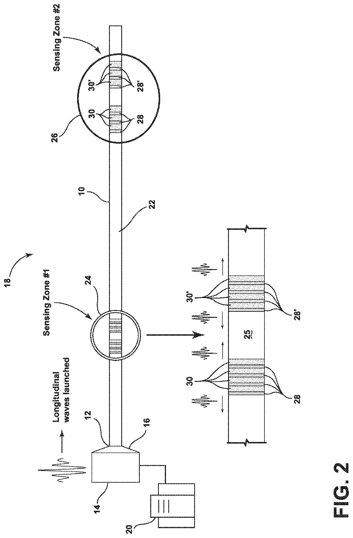
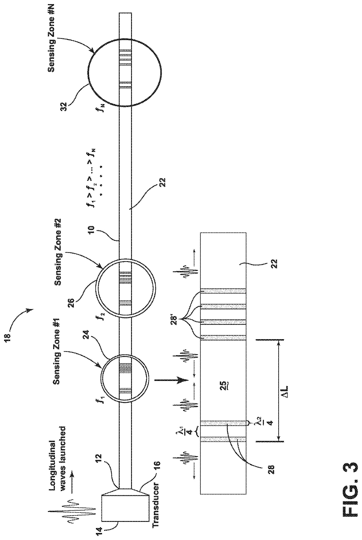
[0023]As discussed herein, the current embodiments include ultrasonic waveguides having a series of sensing zones. Each sensing zone is designed to be highly reflective to a narrow frequency band while being transparent to other frequencies. A transducer launches a longitudinal elastic wave of desired waveform and frequency. The wave propagates down the waveguide, and is reflected from the sensing zone that is tuned to that frequency. By detecting arrival time differences between reflected waves from adjacent reflection features that are separated by a known distance, the temperature at each sensing zone can be accurately determined.

I. Sensing Zones of Dissimilar Materials

[0024]Referring now to FIG. 2, an ultrasonic waveguide is illustrated and generally designated 10. The waveguide 10 is coupled at a proximal end 12 to an ultrasonic transducer 14. A conical transition coupling 16 can be used to focus the ultrasonic energy. The waveguide 10, the transducer 14, and the transition cou...


PUM

PropertyMeasurementUnit
frequencyaaaaaaaaaa
frequencyaaaaaaaaaa
lengthaaaaaaaaaa

Abstract

An improved ultrasonic waveguide for an ultrasonic thermometry system is provided. The waveguide includes a series of sensing zones, each of which is tuned to a specific narrow frequency band. The waveguide is acoustically coupled to a transducer, which launches a longitudinal elastic wave of desired waveform and frequency. The wave propagates down the waveguide, and is reflected from the sensing zone that is tuned to that frequency. Each sensing zone is designed to be highly reflective to a narrow frequency band while being transparent to other frequencies.

Description

CROSS-REFERENCE TO RELATED APPLICATIONS[0001]This application claims the benefit of U.S. Provisional Application 62 / 889,692, filed Aug. 21, 2019, the disclosure of which is incorporated by reference in its entirety.STATEMENT REGARDING FEDERALLY SPONSORED RESEARCH AND DEVELOPMENT[0002]This invention was made with government support under Contract No. DE-AC05-00OR22725 awarded by the U.S. Department of Energy. The government has certain rights in the invention.FIELD OF THE INVENTION[0003]The present invention relates to ultrasonic temperature measurement and more particularly to ultrasonic waveguides for distributed temperature sensing in harsh environments.BACKGROUND OF THE INVENTION[0004]In the control of nuclear reactors, accurate measurement of temperature has safety significance and efficiency implications. Currently, critical process temperatures in a nuclear reactor are measured using either resistance temperature detectors (RTDs) or thermocouples, both of which exhibit signifi...

Claims


Application Information

Patent Timeline
Patent Type & Authority Applications(United States)
IPC IPC(8): G01K11/24G01K11/26G01N29/22
CPCG01K11/24G01N2291/02881G01N29/228G01K11/26G01N29/348G01N29/2462G01N29/07G01N29/024G01N29/4436G01N2291/0421
Inventor CETINER, NESRIN O.CETINER, MUSTAFA S.ROBERTS, MICHAEL J.MUTH, THOMAS R.VARMA, VENUGOPAL K.MONTGOMERY, ROSEMARY A.MURALIDHARAN, GOVINDARAJAN
Owner UT BATTELLE LLC
Why Eureka
Try Eureka