
Two-sided inductive charging coil

Pending Publication Date: 2021-02-18
MICROSOFT TECH LICENSING LLC
View PDF1 Cites 1 Cited by
  • Summary
  • Abstract
  • Description
  • Claims
  • Application Information

AI Technical Summary

Benefits of technology

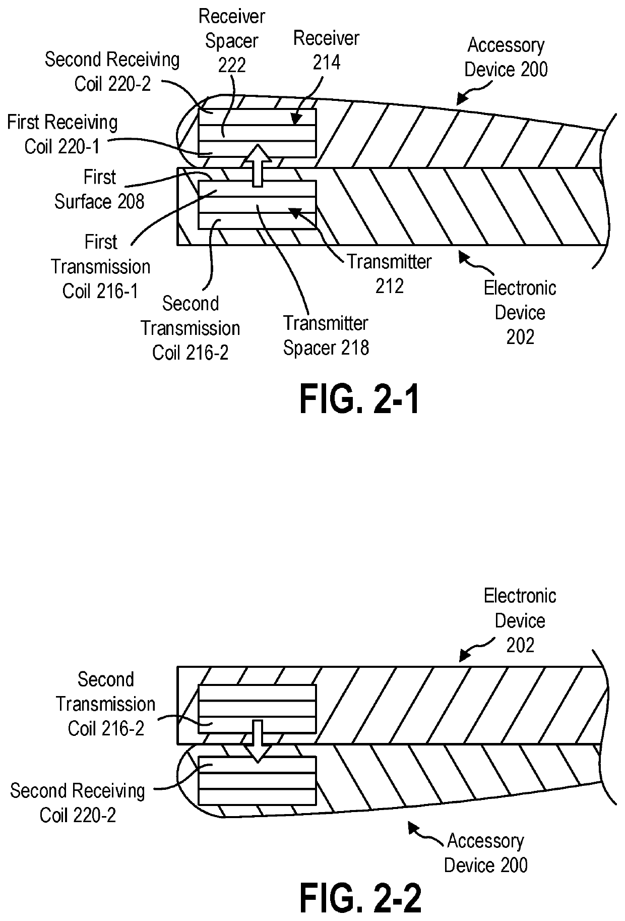
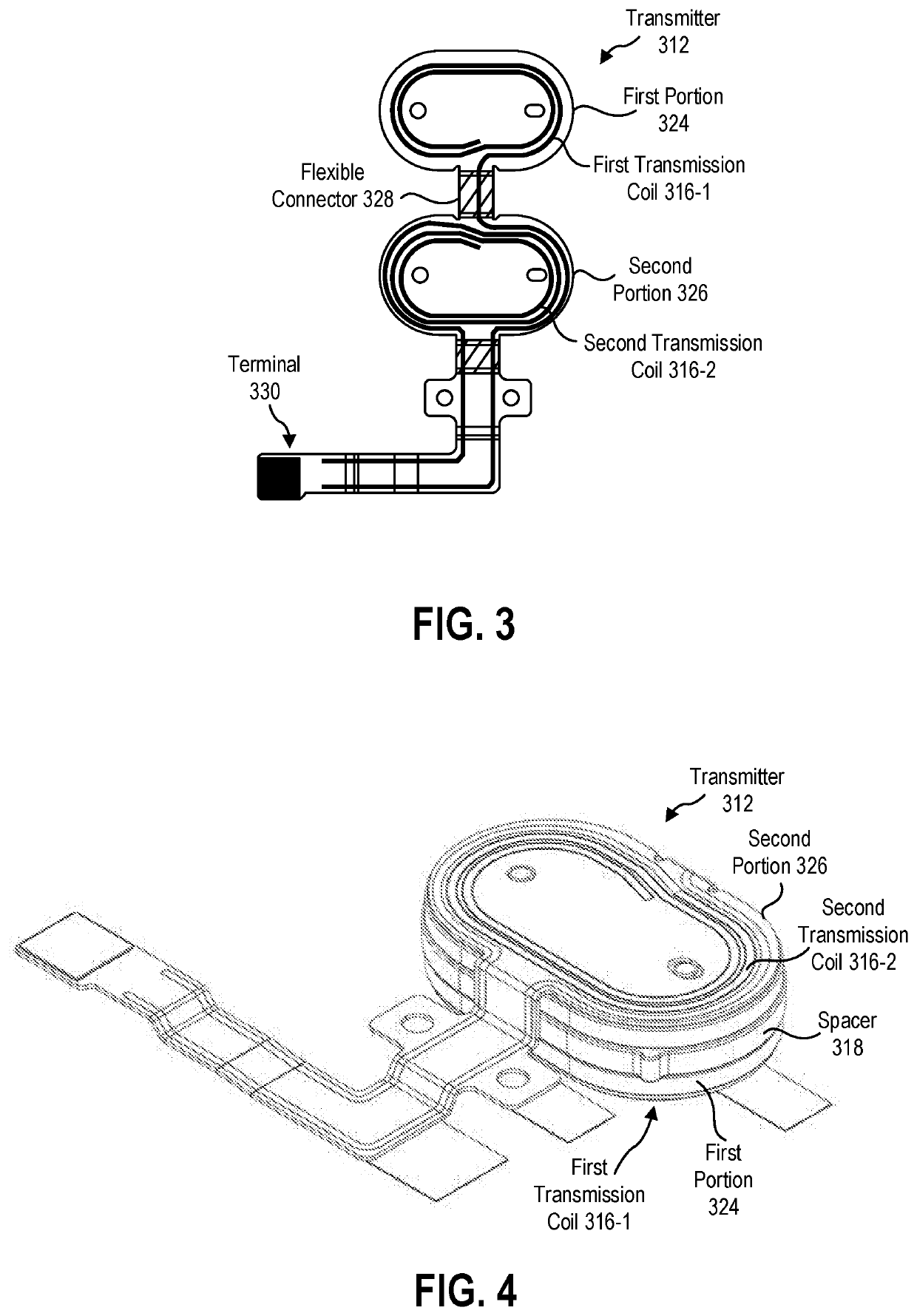
The patent describes a computer with two charging coils placed on opposite sides of the computer. These coils can cause magnetic interference and power loss if they touch. To prevent this, the coils are stacked with a non-magnetic material called ferrite. This setup allows for efficient charging of the keyboard from both sides, reducing the size and power requirements of the coils. The technical effect is improved charging performance without the need for bulky, damaging components.

Problems solved by technology

Magnetic coupling between the coils in the computer (e.g., between transmission coils) could lead to power loss and potential damage to the charging circuitry.

Method used


Image

  • Two-sided inductive charging coil
  • Two-sided inductive charging coil
  • Two-sided inductive charging coil

Examples


Embodiment Construction

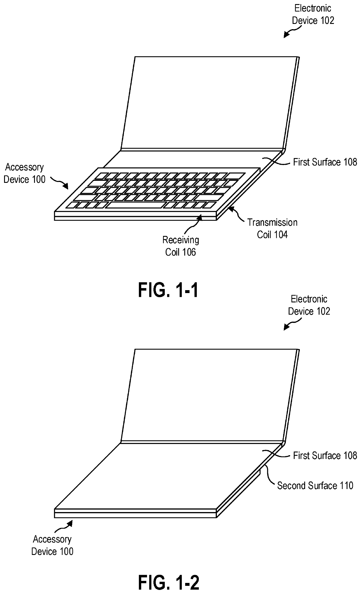
[0023]The present disclosure relates generally to devices, systems, and methods for providing power to an electronic accessory to power the electronic accessory and / or charge a battery of the electronic accessory wirelessly. In some embodiments, the power is provided to the electronic accessory by an electronic device, such as a laptop computer, a tablet computer, a hybrid computer, a smartphone, a smart television, other appliance, an automobile (such as in a passenger compartment of the automobile), or another electronic device. In some embodiments, providing power to the accessory device wirelessly includes positioning the accessory device in one of a plurality of positions relative to the electronic device.

[0024]FIG. 1-1 shows a charging system 101 that includes an accessory device 100 and an electronic device 102 in accordance with some embodiments. As shown in FIG. 1-1, a user places the accessory device100 on a first surface 108 of the electronic device 102 in a charging posi...


PUM


Abstract

A device for inductively charging an electronic accessory includes a first portion, a second portion, and a spacer. The first portion includes a first transmission coil in a first plane where the first transmission coil is configured to generate a first magnetic field, and the second portion includes a first transmission coil in a second plane where the second transmission coil is configured to generate a second magnetic field. The spacer is positioned between the first transmission coil and the second transmission coil and between the first plane and the second plane. The spacer material magnetically insulates the second transmission coil from the first magnetic field.

Description

BACKGROUNDBackground and Relevant Art[0001]Electronic devices commonly utilize wireless accessory devices to allow users to provide inputs to or interact with the electronic devices. Wireless accessory devices have batteries to power the accessory devices during operation. Conventional systems for charging the accessory devices include charging cables, inductive charging coils, or charging cradles. Each of the conventional charging systems require the user to place the accessory device in a particular location, on a particular cradle, or to take an extra step of plugging the device into a cable.[0002]Inductive charging provides a current through transmission coil to generate a magnetic field. Exposure of a second coil of conductive material to the magnetic field induces a current through the receiving coil to wirelessly power an electronic device or charge a battery. Because the power transmission via the magnetic field is related to the strength of the magnetic field, the power tra...

Claims


Application Information

Patent Timeline
IPC IPC(8): H02J50/10H02J50/40H02J7/02H02J7/00H05K3/46
CPCH02J50/10H02J50/40H05K2201/0707H02J7/0027H05K3/4691H02J7/025H02J50/402
Inventor CALLAN, CASEY SEANKRISTJANSSON, STEFAN JONNEVISTIC, DANIEL THOMASKARAVAEV, GEORGEDEILY, MICHAEL FRANCISVOTH, DAVID WILLIAMNAGAMPET, SRINIVAS REDDY
Owner MICROSOFT TECH LICENSING LLC
Learn More